Software Used on this Project
Project Overview
Requirements
The Stratford City project created a major new mixed-use urban centre on a former railway goods yard in Stratford, East London. It is immediately east of the Olympic Park site and was completed in readiness for the London 2012 Olympic and Paralympic Games. Bridge 20 carries the northern access road across the Network Rail tracks which are on a bridge over the CTRL station box.
Constraints
The Network Rail tracks were at a skew to the road alignment which meant the span of the bridge had to be reduced to minimise the cost of the structure.
Substantial utilities were carried across the bridge to provide the Olympic village on the north side of the bridge with electricity, water and telecommunications. This requirement and the need to be able to inspect and maintain these utilities over a railway line without interruption to the rail traffic led to the decision to provide a box girder deck in which the utilities could be carried.
How Oasys proved invaluable
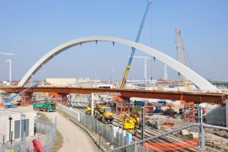
To minimise the effective span, Arup developed a single arch scheme in connection with a torsionally stiff deck box and side cantilevers. This approach was more innovative than a traditional ladder beam and slab deck carried by two arches.
Analysis
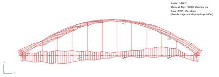
The bridge was analysed using Oasys GSA. Over 18 construction stages were modelled, examining permanent, highway traffic, wind and impact loads using linear and buckling analysis resulting in nearly 200 load cases and nearly as many combination cases.
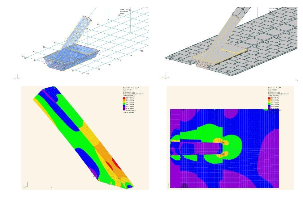
Critical areas such as the bracing diaphragms and arch base were also analysed in detail using 2D finite elements. The complex geometry at the intersection between arch and deck was modelled in 3D and the stress verification was carried out based on the FE analysis.
For this purpose a semi-local model was created, incorporating the 3D FE model into the global beam model. With that method it was possible to take account of the constraint condition for the local model. Loadcases and combinations were still compiled using the global model.
Design
The torsional stiffness associated with a box girder deck made it possible to consider structural configurations with supports along the centre of the deck only. A single central arch with vertical hangers along the median of the bridge was the preferred option.
The shape of the arch was optimised to satisfy structural, architectural and space constraints. To maximise the usable deck space in the “shadow” of the central arch, the width at deck level was kept to a minimum. This was compensated by increased depth, which increased the stiffness of the deck-arch interface for vertical bending. The arch box was widened towards the crown to increase resistance to lateral buckling. For a slender appearance and reduced transverse wind load the depth of the box was reduced while maintaining a near constant area to cope with the axial compression.
The hangers were locked coil closed hangers with fork sockets at top and bottom and an adjustable anchorage at the bottom. Design of the hangers took into account the replacement of any one hanger at one time as well as the sudden accidental loss of one hanger.
The deck was a steel-concrete composite box girder. The steel box girder consisted of a trapezoidal open steel box with cross frames at 3.75m intervals. The construction of the reinforced concrete slab was to be carried out with permanent formwork planks to reduce construction time over the railway line.
Construction
The erection sequence was designed to maximise the horizontal tie force in the steel box girder to minimise permanent tension in the concrete slab.
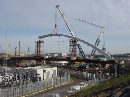
The steel box girder was delivered in pieces to site and assembled via longitudinal spliced joints into units for erection. A total of three units were placed by use of two temporary trestles during a blockade of the railway line. The arch was then also erected in three pieces, with all arch site connections used welded joints.
The stressing of the hangers was designed to lift the deck off the temporary trestles. The side cantilevers were installed after removal of the deck trestles.
Credits
Client: Stratford City Developments Limited (SCD)
Structural Design: Arup
Architect: Knight Architects
Contractor: Morgan Est
Contractors Engineer: Benaim (UK) Ltd
Photographs: Robert Meyer
Renderings: Moxon