Software Used on this Project
Project Overview
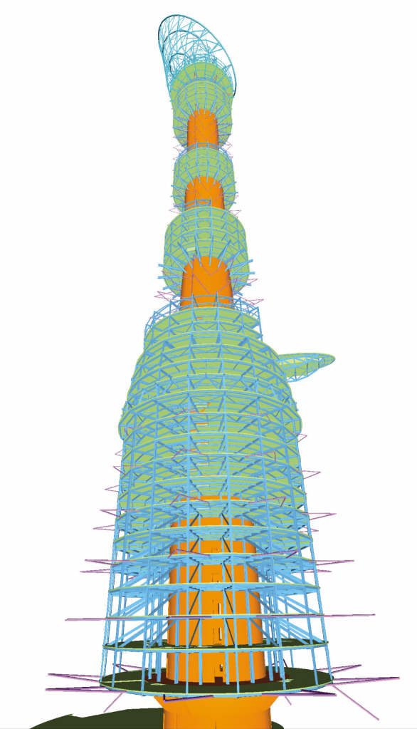
The centre piece of the 15th Asian Games was the Aspire Tower, shaped to represent a colossal torch, which for the duration of the Games held its symbolic flame within the lattice shell that forms the topmost section. At 300m, Aspire Tower is currently the tallest building in Qatar.
The tower includes a large reception and public area on two floors; restaurants and business centre; 17 floors of five-star hotel accommodation; a three floor sports museum; a three floor health club with a cantilevered swimming pool 80m above ground; presidential suites; and a revolving restaurant and observation deck about 240m above ground. A 62m high lattice shell structure on top of the reinforced concrete central core frames the 15MW flame cauldron.
Arup was the structural, mechanical, electrical, fire, acoustics, lift, and wind consultant, working with Midmac-Six Construct, the Qatarian architect Hadi Simaan and the interior designer, Ecart.
How Oasys proved invaluable
Foundations
A geotechnical desk study showed limestone near to ground level, so the initial design was based on a raft foundation. While this progressed, a site investigation was carried out on the deeper geology and rock types – particularly important in view of the magnitude and concentration of load arising from the building form. This confirmed the presence of weak Rus Chalk between the limestone strata. In view of this and the assessment of soil/rock stress in this stratum based on the raft design already under way, the team decided that piling to the raft was needed to ensure adequate load capacity.
In addition to gravity loads, the raft provides resistance to overturning effects under lateral wind and seismic loads. This also ensures there is no tension in the piles or uplift, as the tension effects of overturning are balanced against the vertical load from the tower’s self-weight.
Piled raft analysis
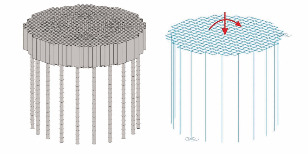
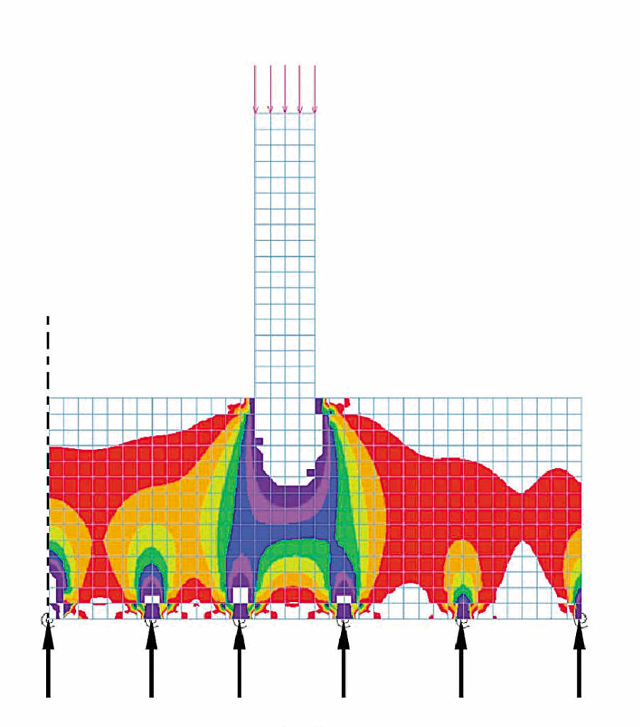
GSA Building was used to analyse the foundation system as it uses an iterative analysis system between two models, one for structure and one for soil. The structure model comprises a GSA grillage model supported on springs at the underside of the raft and also at pile positions at the depth of the pile load transfer length. The soil model comprises a representation of the soil strata, with loaded areas corresponding to spring location in the structure model.
At each stage of iteration soil settlements are calculated by Vdisp, for the spring loads in the structure model. The settlements are then used to reset the spring stiffnesses in the structure model. The process is continued until vertical movements and load distributions match, providing a unique analysis for each load condition.
To assess local effects such as load spread beneath the core walls, the through thickness flexibility of the raft over an annular sector was also modelled axis metrically, using loads and spring stiffnesses output by GSA. A lower/upper bound design approach allowed for the range of parameters involved including soil, concrete and design loads.
Using the results of the raft analysis, bored cast in situ piles were limited to a maximum 1.2mm diameter to suit local practice, extending through Rus Chalk to the better limestone below. The piles were cast in grade C32/40 concrete for the necessary design strength. The 37.3m raft diameter was determined by the need to spread the entire tower load delivered by the core, to limit bearing pressures to appropriate levels under the raft, in the Rus Chalk and on the piles.
Super Structure
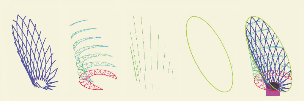
A 62m high steel diagrid frame tops out at 300m above the reference ground level. The diagrid forms the lateral stability system for the upper part of the building, and also supports the cladding down to the restaurant floors. The diagrid springs from a substantial concrete frame: a 1m wide and 1.5m deep circumferential ring beam supported by nine concrete columns each approximately 1m by 1.5m arranged radially on top of the concrete core wall. The top of the concrete core wall is approximately 233.3m above lobby level, the top of the frame some 4.5m above that.
The primary loadbearing elements of the diagrid shell are the circular hollow sections (CHS), which vary from 610mm diameter near the base to 457mm diameter at the top. The shell is restrained laterally by a series of horizontal trusses outside the “petal” at 8.1m vertical centres, spaced to coincide with the cladding system’s horizontal support elements and sized to accept horizontal loads. The upper levels of trusses are in 500mm x 200mm rectangular hollow sections (RHS) and 300mm x 300mm square hollow sections (SHS), while the lower levels use just 300mm x 300mm SHS.
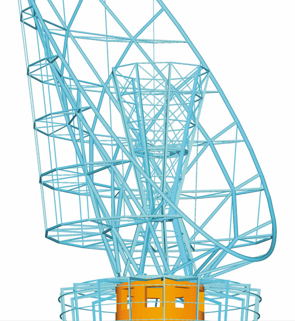
The vertical loads from the cladding are carried by 18 hangers, 120mm x 120mm SHS, equally spaced around the building perimeter. The outer booms of the trusses span between them for vertical load, whilst they restrain the truss booms against buckling out of plane. At the head of the outer plane there is an “eaves trimmer” – the rim of the “petal” – formed from 610mm diameter CHS. It carries the vertical load in the hangers, between the heads of the diagrid elements and acting in biaxial bending to resolve the forces in the diagrid elements that do not node out regularly at the ring. In addition the eaves trimmer carries wind load and/or vertical load from the cladding connected directly to it.
The diagrid is a tall, relatively light structure that is subject to significant lateral loads. As a result, substantial tension forces are generated within it under certain load situations. The steel structure is able to deal with these, but this behaviour also gave rise to the potential for physical uplift and considerable movement of the base of the shell from the supporting structure. To cater for this effect, the base of the lattice shell is attached to the top of the core by clusters of vertical prestressed bars extending down into the body of the core. These clusters consist of either four or six prestressed bars, each stressed up to 3200kN, and anchoring 300mm thick baseplates of the lattice shell nodes to the supporting concrete.
Installing these bars and the associated anchor plates, ducts, and antibursting reinforcement was a considerable challenge for the contractor.
Structural Action
Vertical Loads
At the diagrid rim, the hanger loads are collected by the eaves trimmer. This is curved in plan and elevation, so there is no direct line-up between the hangers and the diagrid members. The eaves trimmer must therefore carry torsion as well as bending moments in two directions, shear in two directions, and axial force. The splice connections in the eaves trimmer are bolted connections offset from the diagrid members. The diagrid CHSs then carry the loads in compression to the head of the core where they are resisted by the bearing of the connection nodes onto a grout layer on the head of the core walls.
The building’s asymmetrical shape means that the cladding and self-weight loads on the high side are significantly greater than on the low side. In addition to the overall compression, this generates an overall bending moment in the diagrid shell system, carried in the same way as the moments generated by wind load in the wide direction.
Horizontal Loads
The wide direction is the critical direction for wind loading because (a) the widest face area is exposed to the wind, and (b) the structural depth available to resist the loads is at a minimum.
The wind applies pressure to the cladding system, which spans 8.1m vertically between horizontal trusses. The horizontal trusses collect and redistribute the horizontal component of the wind load and transfer it to the petal diagrid, which resists by push/pull action in the inclined CHS members and transfers it down to the connection at the head of the core. Each level of horizontal truss contributes to the push/pull in the diagrid CHSs and so the magnitude of the forces in the diagrid increases down the structure until it reaches a maximum in the level immediately above the head of the core. The forces distribute themselves elastically through the grid structure so that there are compressions on the downwind side of the shell structure, tensions on the upwind side, and opposing pairs of compressions and tensions in between.
Horizontal loads in the narrow direction of the petal, while they give rise to lower overall forces in the structure, they do give rise to an overall torsion in the diagrid that must be resisted.
Conclusion
Design and construction of the main structural elements were completed within the 21 months specified for the tower, enabling it to fulfil it’s designated function for the 2006 Asian Games.

