Software Used on this Project
Project Overview
A Port Authority wanted to gain an understanding of the likely impact from crane and bulk cargo loadings on a number of historic quay walls (over 150 years old gravity retaining walls) within impounded docks, and so commissioned Arup to undertake a desk based assessment of the stability of their existing walls.
The aim of the project was to understand the impact of a number of different crane and bulk loading scenarios on the quay walls. This would inform future work and loading restrictions to ensure the long-term stability of the walls. It was important to the client to produce a simple output which could be interpreted easily by nontechnical staff.
How Oasys proved invaluable
Outline of Approach
The level of sophistication of the approach had to be tailored to the client’s budget and technical restrictions for this stage.
Static equilibrium analysis using Oasys Greta was identified as appropriate for the assessment due to the speed of analysis and ability to modify for multiple loading scenarios. An un-factored analysis was done, as the Port did not want to compare their historic walls to modern design standards. This was supplemented by consideration of the slope stability of the walls using Oasys SLOPE.
As it was a desk based assessment, confirmatory site works could not be undertaken, and so assumptions needed to be made. This included modelling theoretical wall profiles based on historic construction drawings of the 150 year old walls. No project specific ground investigation information was available so nearby information was used to provide an estimate of the likely ground conditions.
An understanding of the effect of the crane loads on the stability of the wall as they moved closer to the edge of the quay wall was presented to the client.
Overview of Challenges/Constraints
Throughout the process, a number of challenges presented themselves, and had to be overcome. The key challenges faced are outlined below:
Discrete Loading Areas of Loading Behind the Wall
The loading scenarios applied behind the wall were applied over discrete areas from crane outrigger pads and isolated areas of bulk load (an example of this is shown in Figure 1). Unfortunately, Greta does not have a natural mechanism to model this, and can only apply surcharges as a UDL behind the wall or in front of the wall, or a line load on top of the wall as shown in Figure 2.
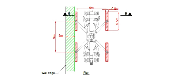
Figure 1 – Typical illustration of discrete loading applied behind wall by outrigger pads
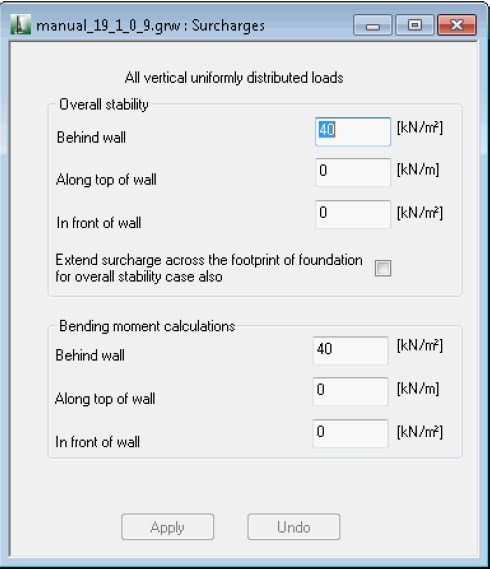
Figure 2 – Extract from Oasys Greta manual showing methods of applying loadings
This was resolved by applying the equivalent thrust forces acting on the back of the wall as negative anchor loads, using the method contained within PD 6694-1:2011 [1]. Figure 3 shows the visualisation of the conversion of the traffic loads to a thrust force behind the wall. This method not only provided an equivalent force to apply, but also the specific depth at which the resultant thrust force would be applied on the back of the wall. It should be noted that this was only considered applicable when the loads were behind the wall, and when loads were applied directly on top of the wall this was simplified as an equivalent line load on top of the wall.
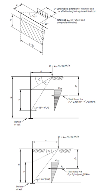
Figure 3 – Method used to apply discrete loadings from crane wheels and outriggers as negative anchor loads in Oasys Greta (extract from BSI, PD 6694-1:2011)
Figure 4 then shows a screenshot from Oasys Greta, with the equivalent thrust force being applied to the back of the wall as a negative anchor load (i.e. an anchor pushing towards the front of the wall, rather than pulling back towards the soil).
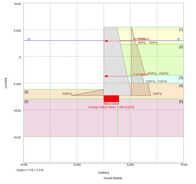
Figure 4 – Screenshot from Oasys Greta showing how negative anchor loads were applied to the back of the gravity retaining wall to model the effective thrust force applied by crane outrigger loads at surface.
Sliding FoS Equation Inconsistency
When applying the negative anchor loads, the safety results in Sliding were peculiar – the FoS in sliding increased when a larger force was applied which contradicted common sense. Upon investigation the program equation was inconsistent with the application of a negative anchor load, calculating the net horizontal force in the same direction as the passive force, via the following equation;
FoS in Sliding = (Sliding resistance) / (Passive force – Active force)
This equation results in the negative anchor load contributing towards the reduction in Passive Force, and hence reducing the denominator in the equation, which should represent the destabilising force and should increase in this scenario. To be consistent, the equation should be presented as;
FoS = (Horizontal passive force + sliding resistance) / (Horizontal active force)
This equation correctly reduces the numerator stabilising force when a negative anchor load is applied, and so reduces the Factor of Safety in sliding in this scenario.
As the forces were calculated correctly in Greta, these were taken from the output and applied to manual calculations of this equation in a spreadsheet.
Overturning Towards Heel
Issues were experienced due to high passive forces in front of the wall, and the assumption within Greta that these were fully mobilised.
In some scenarios, where logically the forces behind the wall were clearly larger than those in front of the wall, the mobilisation of full passive resistance forces in the static equilibrium model suggested overturning towards the heel, which was not a realistic scenario.
To resolve this, the passive force of the soil in front of the wall was limited by manually estimating the mobilisation of passive force in front of the wall and reducing the level of passive soil to reflect this.
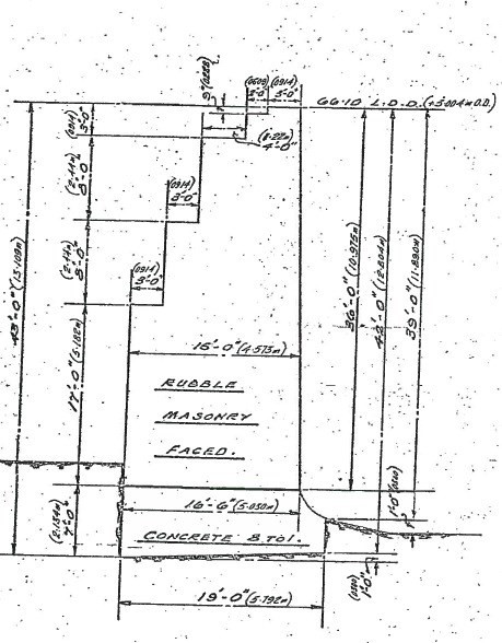
Wall Shape
The walls under consideration had unique cross-sections which could not be modelled accurately within Greta. An example of one of the walls is shown in Figure 5. Simplified cross sections were applied in line with the allowable dimension in Greta, while manual calculations were done to equate the weight of the wall to ensure the same total weight of wall was modelled and the same resultant load location was applied, so that the effect on bearing, overturning and sliding results were modelled as accurately as possible.
Key Findings and Further Work
The assessment gave the Port Authority an understanding of the impact of the loading scenarios on their existing quay walls, and how hard they were being worked in terms of factors of safety in overturning, sliding and bearing capacity, as well as slope stability.
The process identified that the bearing capacity was the critical mechanism for all scenarios, being the closest to a generally acceptable factor of safety out of those considered. A pragmatic output was provided to the client which highlighted where operational restrictions may be required, and provided estimations of the factors of safety at a variety of loading setbacks for the client’s consideration. This was also provided to the client in a graphical depiction, however these drawings contain information that are confidential.
It was highlighted to the client that, as this was a desk based assessment, further work should consider undertaking site specific investigations to determine accurate parameters for a closer comparison to the realistic scenario.
This approach was tailored to the clients’ specific needs and subsequently led to repeat commissions to do a similar assessment at another port owned by this authority.
Future Developments
During the course of this assessment, the number of challenges that were faced were successfully navigated by closely cooperating with the Oasys support team.
Following on from this, updates to Greta will include a more flexible inbuilt method of applying discrete loading to the wall and a method to overcome the incorrect rotation towards the heel by introducing stages where the passive resistance is automatically reduced to achieve equilibrium and more realistically reflect the scenario. This process is currently ongoing.
References
[1] BSI, PD 6694-1:2011, Recommendations for the design of structures subject to traffic loading to BS EN 1997-1:2004.