News
Stay up to date with the latest news from Oasys, including software releases, product updates, events, webinars, partnerships, and company announcements.
Oasys
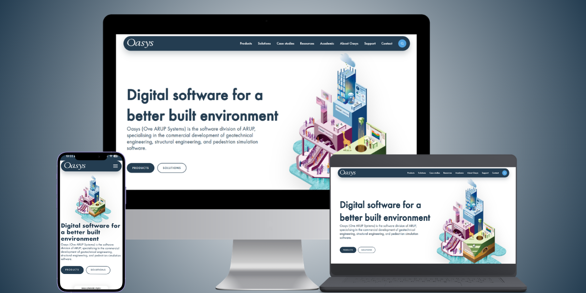
A refreshed Oasys website built with you in mind
Posted April 28th 2026
We’re excited to welcome you to the new and improved Oasys website. Our refreshed site reflects our ongoing commitment to making it easier for you…
Read More
Oasys
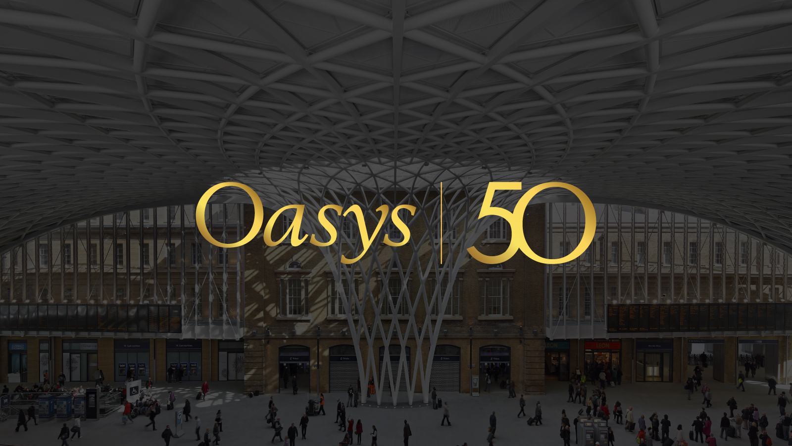
Celebrating half a century of software development
Posted April 16th 2026
50 years of Oasys This year, we proudly celebrate 50 years of pioneering digital solutions for the built environment. Established in 1976, Oasys has…
Read More
Geotechnical engineering
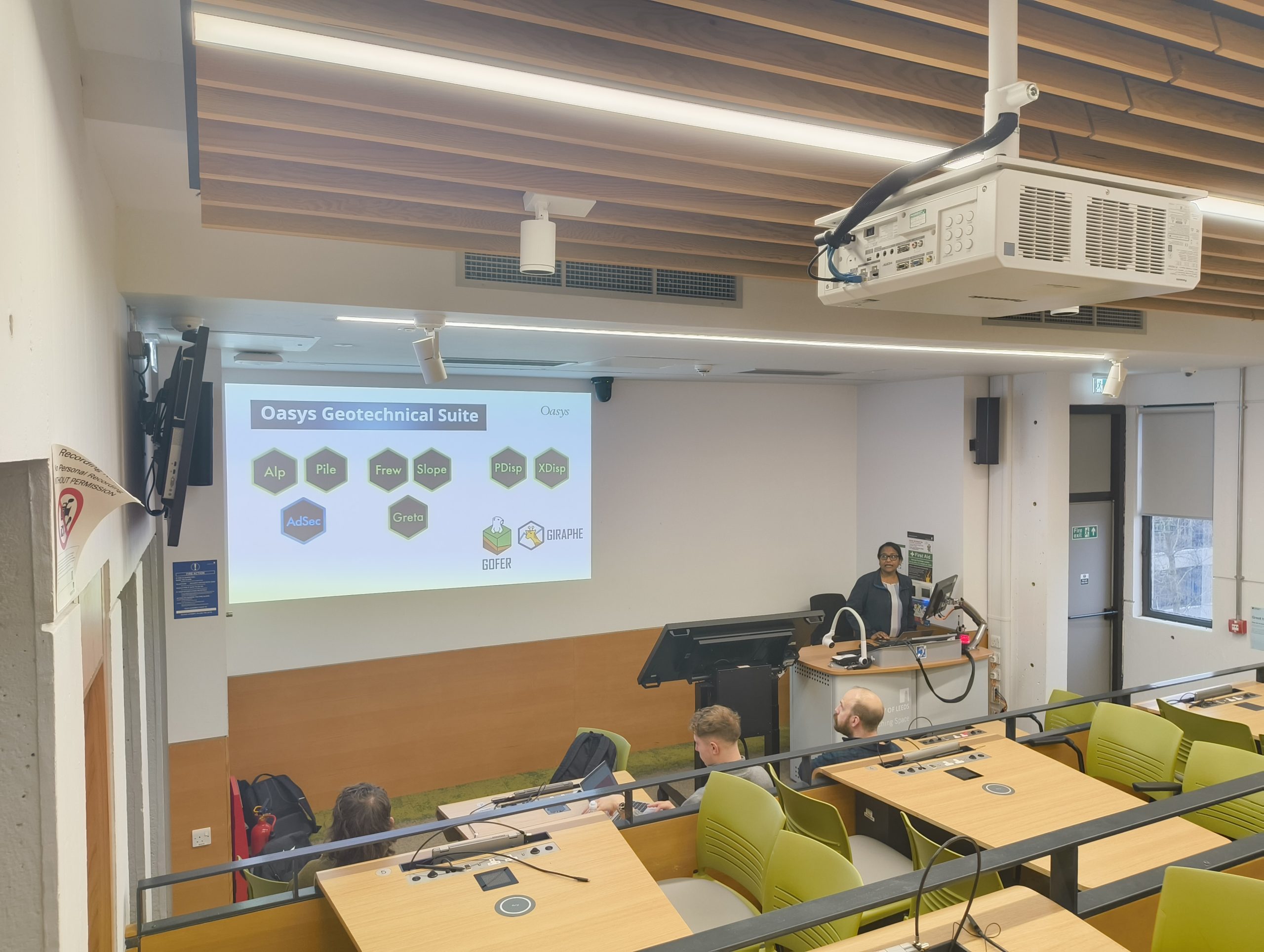
Bringing real‑world ground engineering to the University of Leeds
Posted March 27th 2026
The Oasys Geotechnical team recently visited the University of Leeds to deliver a guest lecture to students on the MSc Engineering Geology programme, alongside colleagues from Arup’s ground engineering team. …
Read More

Geotechnical engineering
Supporting the next generation of Geotechnical Engineers at the University of Birmingham
Posted March 4th 2026
In February 2026, the Oasys Geotechnical team visited the University of Birmingham to deliver a presentation and practical workshop showcasing the capabilities of the Oasys Geotechnical Suite. The event supported students in developing…
Read More
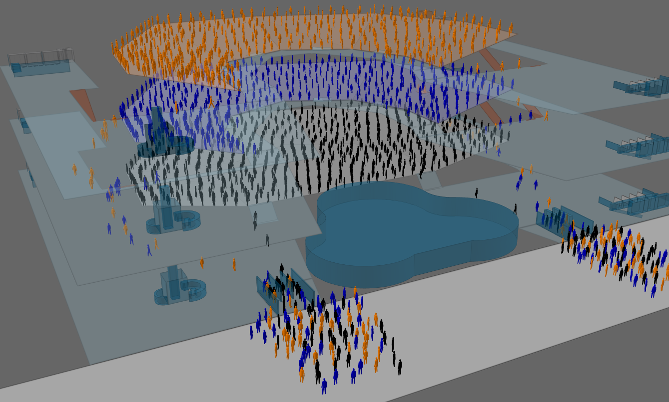
Pedestrian simulation
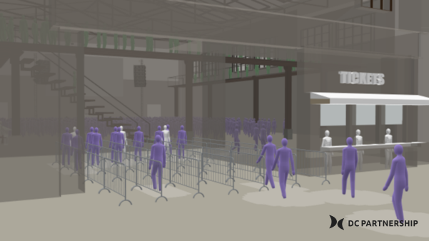
DC Partnership’s CrowdEx team levels up with Oasys MassMotion
Posted February 13th 2026
As part of their expansion into crowd experience and safety with CrowdEx, we’re thrilled to share that we’ve welcomed DC Partnership as a valued client and as Oasys MassMotion specialists. DC Partnership is an Australian…
Read More
Oasys
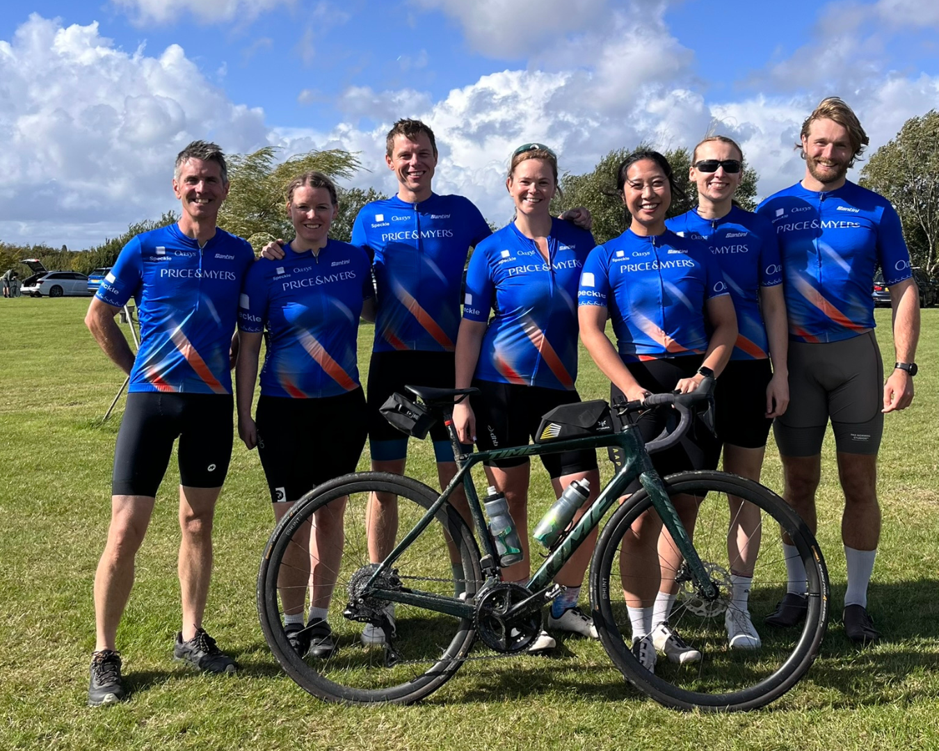
Supporting our clients: Price & Myers cycling team
Posted November 7th 2025
In early September, eight members from Price & Myers cycled the 79km fastest team competition in Sussex for the annual Forcia Limited Building Life Cycle event supported by Lockton. Oasys were proud to sponsor the cycling shirts that the team wore…
Read More
Structural engineering
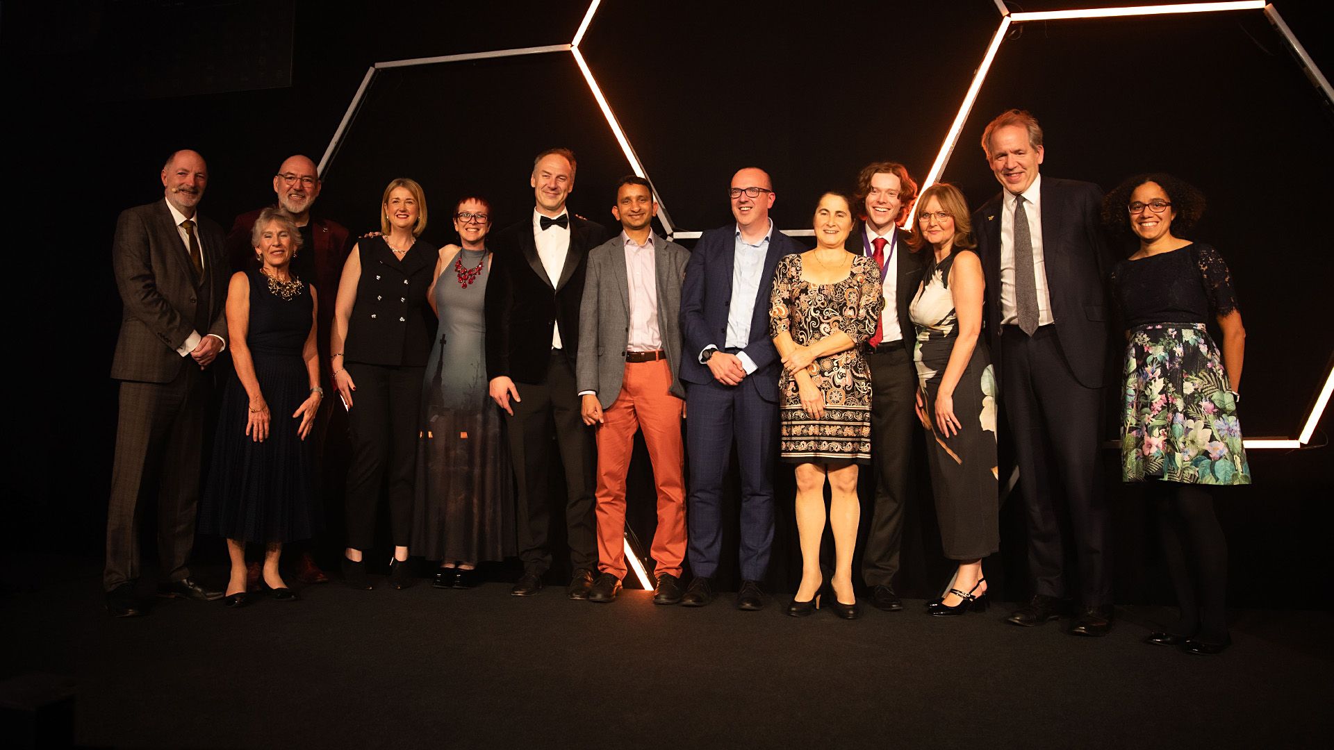
Ground breaking algorithm in Oasys GSA wins Innovate UK Golden Award
Posted November 7th 2025
We are delighted to announce that Arup and the University of Manchester have been honoured with Innovate UK’s prestigious Golden Award for ‘Driving Innovation for the Future’ at the 50th…
Read More
Pedestrian simulation
Shaping the future of pedestrian simulation with our champions
Posted June 2nd 2025
We’re pleased to announce that we’re strengthening our partnership and collaboration with predictive modelling simulation technology partner, SimWell. As we look ahead to the end…
Read More

Geotechnical engineering
You asked, we listened: Discover dynamic graphing with Oasys Giraphe
Posted November 4th 2024
Your feedback is essential to our software development process, and we listened to you. Since the launch of Oasys Giraphe, we’ve been dedicated to ensuring it meets your needs and…
Read More
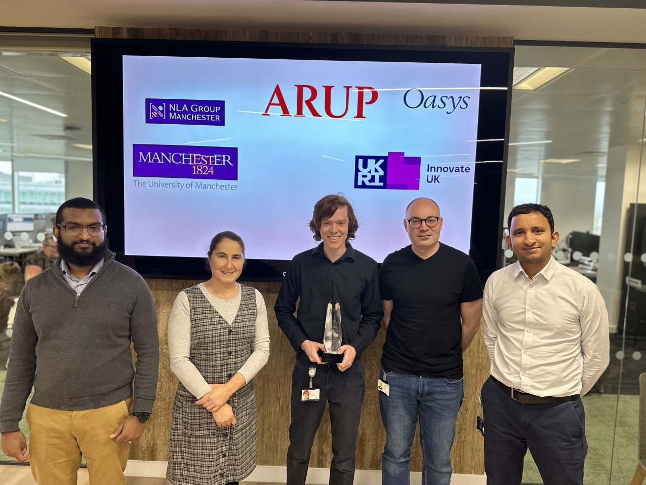
Structural engineering
Arup and University of Manchester win Innovate UK Technical Excellence Award
Posted December 20th 2023
We are delighted to announce that in collaboration with the University of Manchester’s Numerical Linear Algebra group, we have won the ‘Technical Excellence’ award…
Read More
Pedestrian simulation
Oasys MassMotion wins award for Best Innovation at the CogX Awards
Posted March 18th 2022
We are proud to announce that pedestrian simulation software Oasys MassMotion has been recognised for its valuable contribution to projects and the impact it has had…
Read More