Software Used on this Project
Project Overview
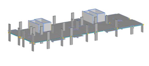
During the work on several residential masterplans in London, Arup developed a digital workflow for the design of flat slab RC frames, fully based on Oasys GSA analysis results, implementing the use of GSA Application Programming Interface (API) and the GSA-Grasshopper plugin. The masterplans consist of 5 – to 32 – storey RC frame blocks, sharing a common basement and podium levels, were fully designed using GSA analysis results. To enhance design efficiency of repeatable floorplates, the team developed specialised automation tools tailored specifically for irregular grid structures which cover the bending reinforcement provision and punching shear checks in flat slabs. The workflow consists of several scripts including column, pilecap and flat slab design, as well as scripts automating creation of GSA models generated from CAD/BIM files using GSA-Grasshopper. These tools have now been successfully tested on several projects, significantly accelerating the design process. The script best presenting many great features of GSA is the Flat Slab Design Tool.
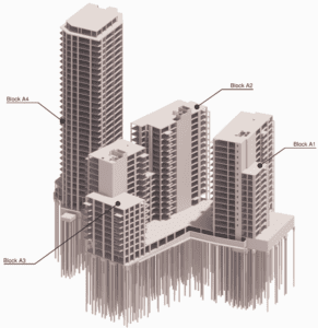
Example RC frame designed using the flat slab design tool
How Oasys proved invaluable
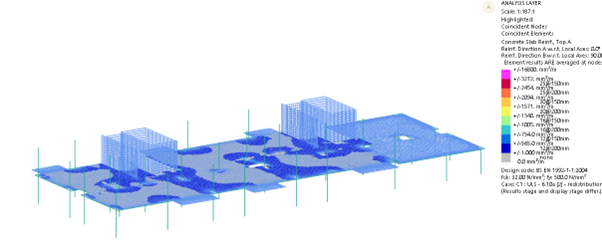
The Flat Slab Design Tool is focused on the automation of the post processing of Oasys GSA analysis results with the use of Grasshopper and Visual Studio scripts. The entire process is centred around the results extracted from a local, single floorplate GSA model, which is generated automatically from a global Revit model. GSA API is used to extract GSA forces and hole, slab and penetration geometry from a GSA model. As a part of that process an envelope of 2D Concrete Slab Reinforcement results is extracted from the model, and any nodal peaks above a user-specified base mat of reinforcement are identified by using GSA-Grasshopper to interpret the model geometry for bending steel checks, finding the nodes which require additional reinforcement, grouping them together based on specified proximity, to form patches of additional reinforcement. Then, the values are averaged out, and drop–in reinforcing bars are specified for top and bottom layers in addition to the base mat.
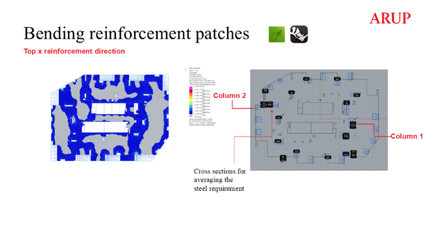
Example floorplate – design of the additional top steel patches
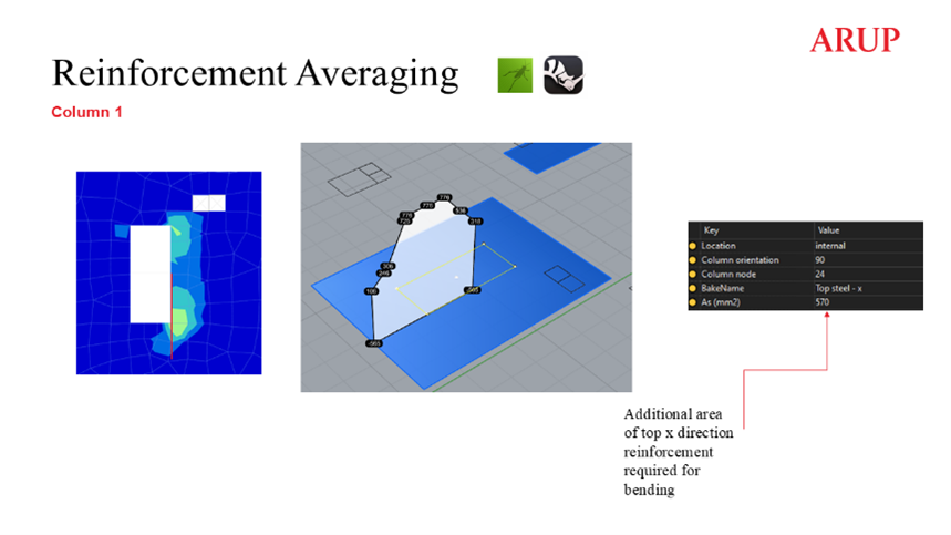
Example floorplate – averaging process for additional bending reinforcement
An additional bending reinforcement check is automatically conducted for edge and corner columns calculated as per BS EN 1992-1-1 9.4.2 (1) requirement to provide the reinforcement for the elastic column moments within b effective. The computation is based on the elastic column moments and slab geometry extracted from the GSA model to identify the edge and corner column.
The additional reinforcement checks extracted from the GSA are then used as an input for Visual Studio punching shear checks around columns conducted using Punchear, to account for additional shear capacity from the bending reinforcement in the hogging zones. The punching shear checks are based on the column forces, moments and geometry, including extraction of the slab voids, all of which are extracted from the GSA model using the API. The script finds a critical load case and iterates through increasing the drop in reinforcement patch size and bar diameter, before adding shear links. The next step is the iteration of the required number of perimeters and diameter of links within specified arrangements. The script continues iterating the reinforcement provision until a desired utilisation is reached or the checked area is found to be unable to be reinforced.
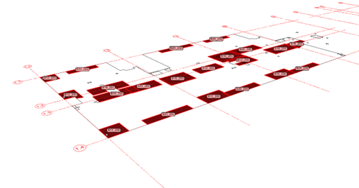
Finally, an automated reinforcement detailing intent is produced in Rhino, covering top and bottom additional reinforcement patches and shear links arrangement. The Rhino RDIs have been developed to work with both traditional 2D detailing and to form the basis of automated 3D detailing. The RDIs are overlaid against GSA 2D Concrete Slab Reinforcement contour plots using GS-Grasshopper
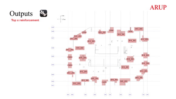
Example RDI output
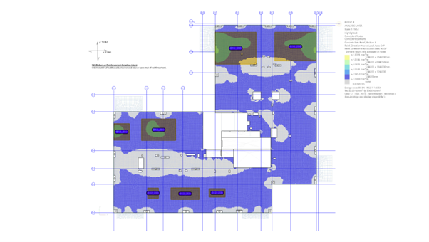
Validation of script results using GSA RC Slab Designer contour plots –bottom reinforcement patches in addition to the base mat
Validation of script results using GSA RC Slab Designer contour plots –top reinforcement patches in addition to the base mat
Alongside the RDI, an output GSA file is created for the validation of the results. Final utilisations, classification of column types (internal, edge, corner or re-entrant corner) and specified links arrangements, are written as User Modules for a convenience of visual checks of the results simplifying the identification and resolution of challenging areas.
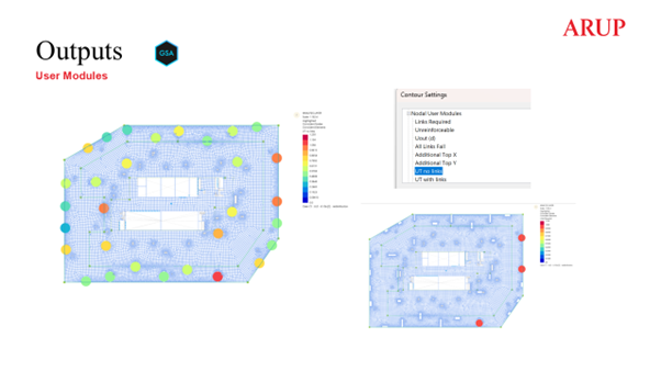
Script outputs written as GSA User Modules
The Flat Slab Design Tool has been implemented in the design of simpler typical floorplate flat slabs but also in the design of basement and transfer slabs with several steps and more complex geometries, drastically reducing the volume of manual checks. The process has been successfully tested on several projects in conjunction with traditional 2D detailing as well as a part of a 3D automated detailing workflow. The flat slab workflow is used alongside RC Column Designer which implements the GSA API to iteratively size and optimise rectangular RC columns based on the results from global GSA models.
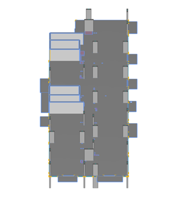
Example A – constructed slab designed using the flat slab design tool
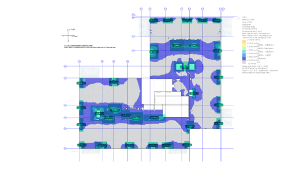
Example A – GSA floorplate model
Example A – GSA RC Slab Designer GSA results for top steel
Example A – final script output RDI
Example B – GSA floorplate model
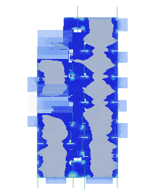
Example B – GSA RC Slab Designer GSA results for top steel
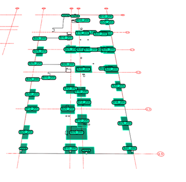
Example B – final script output RDI
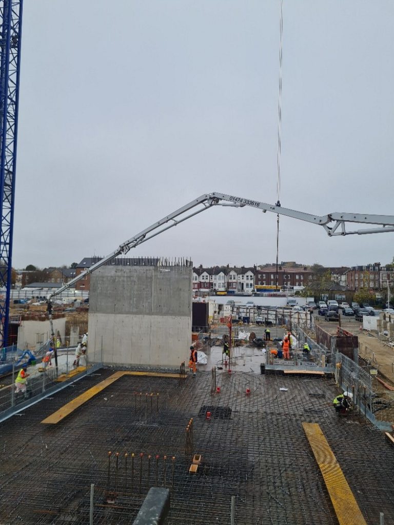
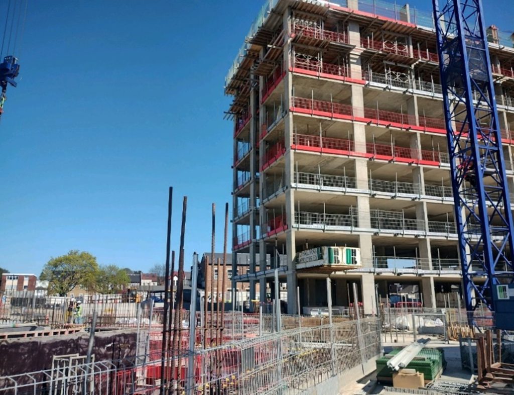
Example – slab designed using the flat slab design tool in construction (additional steel patches as per RDI above)
Summary
The flat slab design tool based on GSA Concrete Slab Reinforcement tool automates the post-processing of GSA results with Grasshopper and Visual Studio scripts, focusing on bending reinforcement and punching shear checks of irregular grid structures. The tool iterates through reinforcement adjustments and shear links arrangements to produce an automated detailing intent in Rhino. A GSA output model with User Modules is created to validate the accuracy of the results.
“The flat slab design tool has been found to significantly speed up the design process and reduce the number of manual checks. The workflow has been successfully tested on several projects and shows potential for broader applications such as design of stability system concrete walls using the tool to interpret GSA 2D Concrete Slab Reinforcement.”
We’d like to thank Arup Structural Engineer Karolina Makarewicz for sharing this work with us.
For more information about Oasys GSA, head to the product page or register your interest to speak to a member of the team.