Case studies
Explore real‑world engineering case studies showcasing how Oasys software is used to solve geotechnical, structural, and pedestrian modelling challenges.
Featured case study
Pedestrian simulation
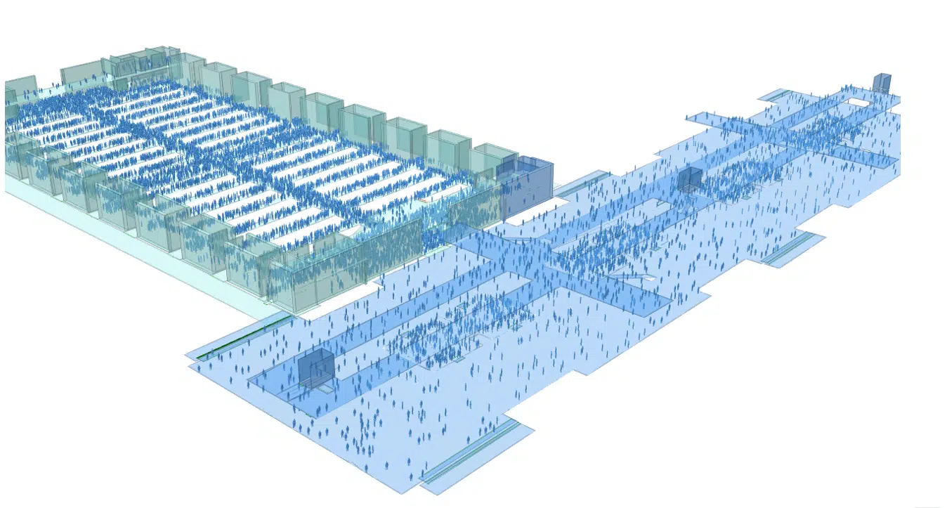
Delivering fire safety solutions for mega-span exhibition buildings
Arup delivered fire safety solutions for a major exhibition complex in China using innovative design and simulation. By applying Oasys MassMotion and ETFE membrane strategies, they achieved safe evacuation, maintained open spaces, and optimised performance through targeted, sustainable fire engineering. [oasys-software.com]
Pedestrian simulation
Delivering fire safety solutions for mega-span exhibition buildings
Structural engineering
Strengthening structural connections in more ways than one: Castle Meadow Campus roof replacement
Structural engineering
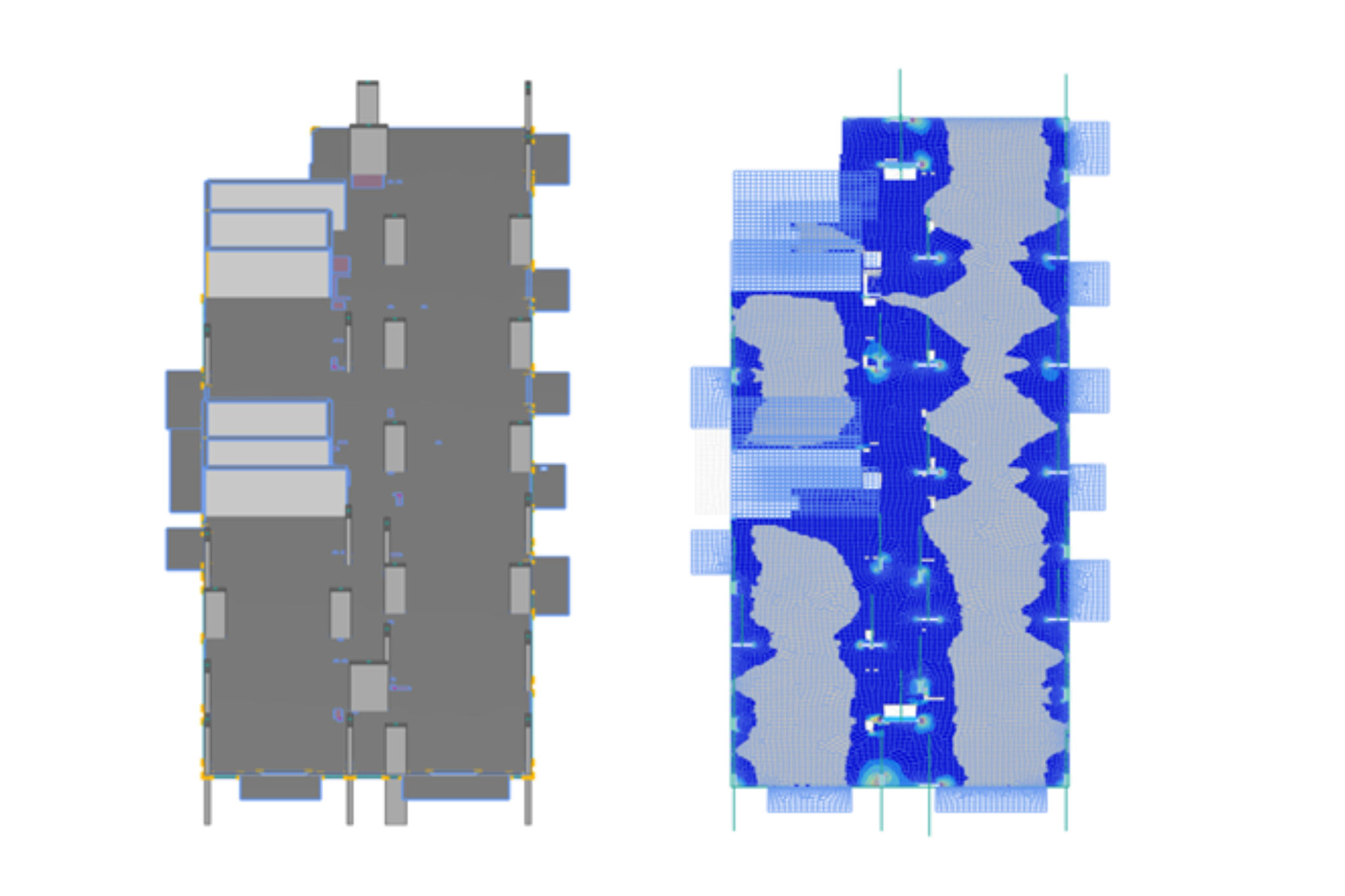
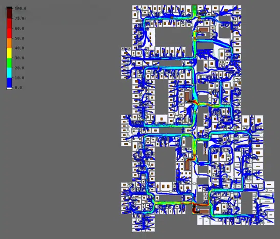
RC flat slab automation: Iterative post-processing of Oasys GSA results
Geotechnical engineering
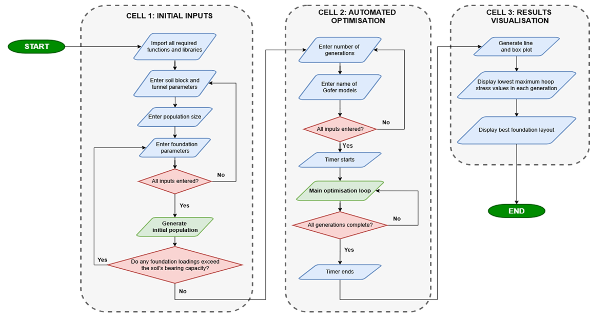
Investigating automated optimisation of foundation design
Pedestrian simulation
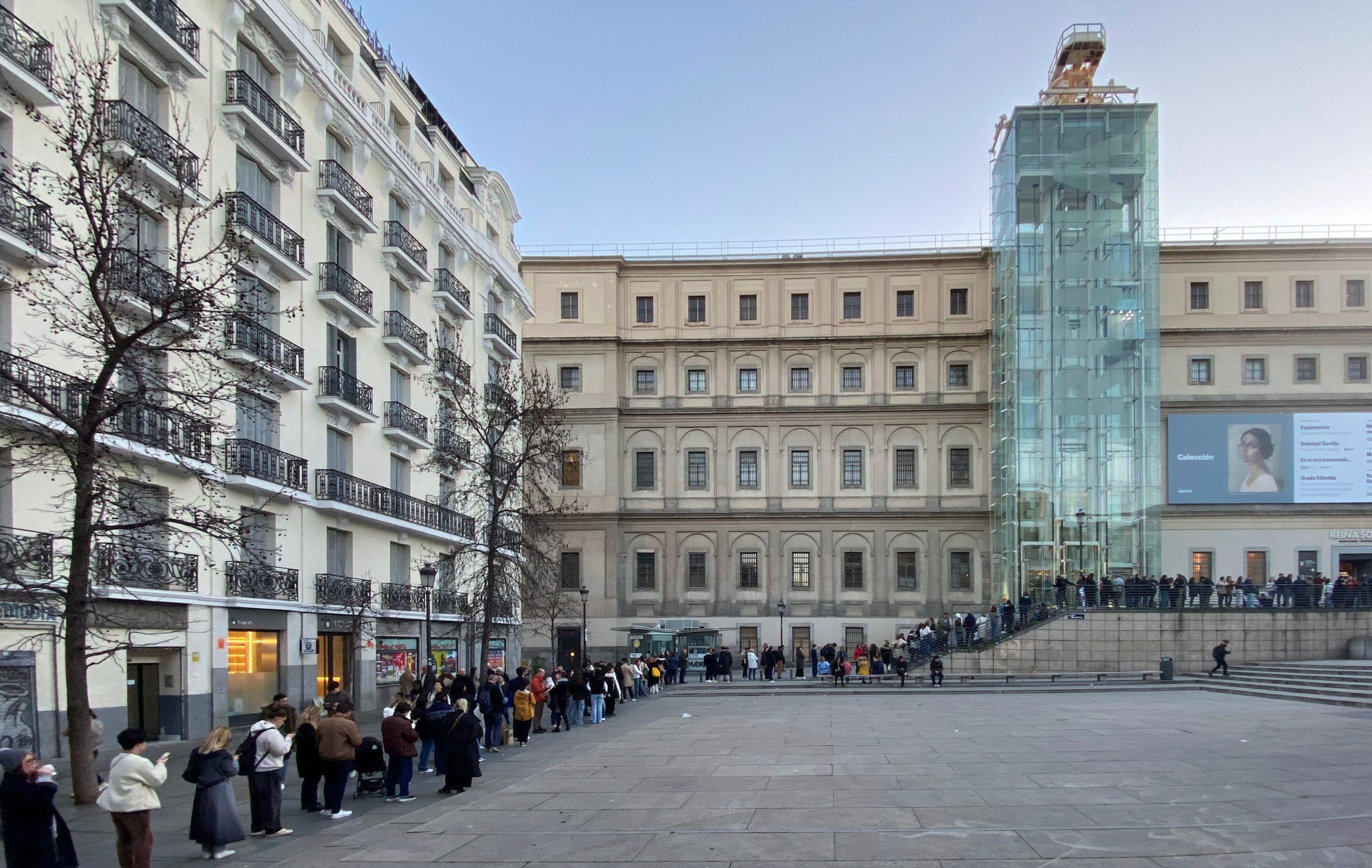
Improving visitor experience at the Reina Sofía Museum in Madrid
Structural engineering
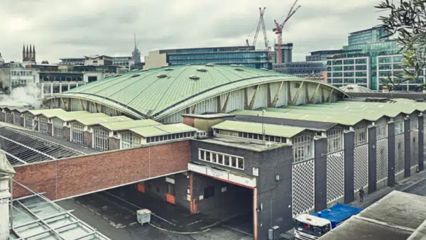
Leveraging detailed structural analysis to determine a “do nothing” approach for sustainable preservation of Smithfield Poultry Market roof
Geotechnical engineering
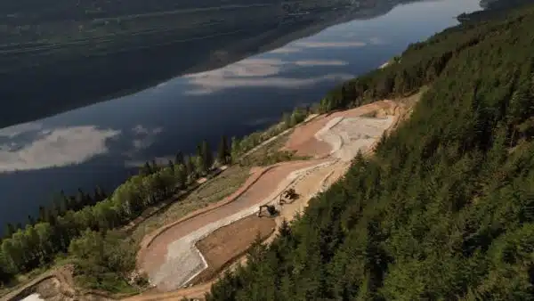
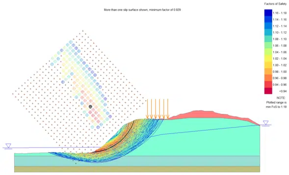
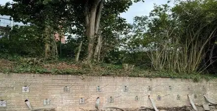
Coire Glas exploratory works – detailed slope stability analysis of a spoil storage area
Structural engineering
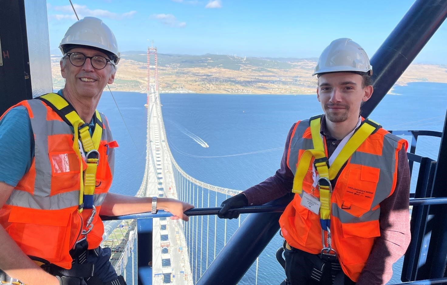
How Arup used Oasys Structural software to verify the design of the 1915 Çanakkale Bridge
Structural engineering
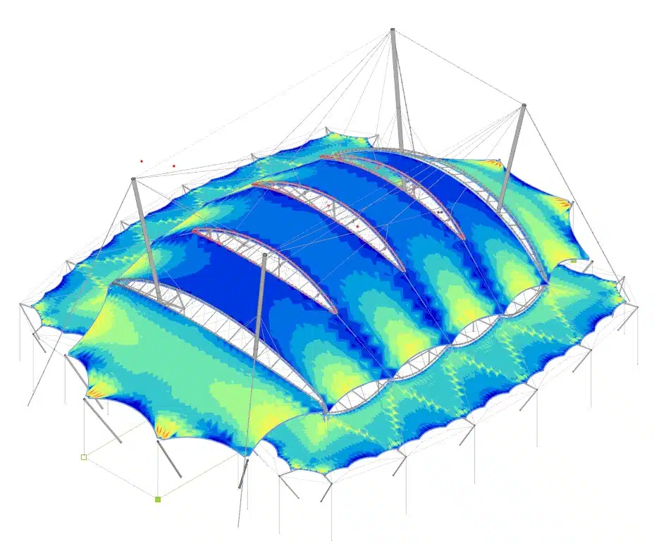
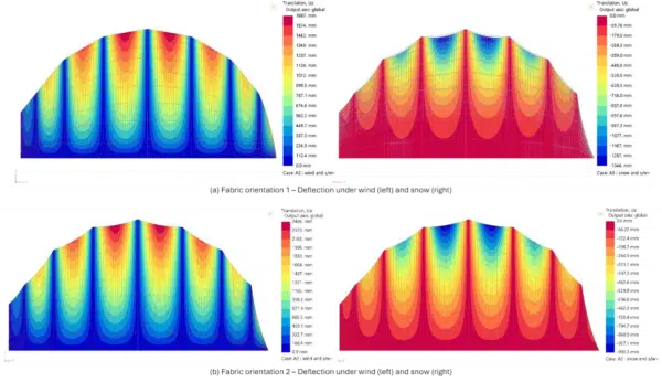
Parametric design of fabric structures using Oasys GSA-Grasshopper: University of Glasgow MEng project case studies
Geotechnical engineering
The future of geotechnical engineering – Oasys Gofer vs traditional FEA methods
Geotechnical engineering
Harnessing digital tools for advanced slope stability and flood embankment design
Structural engineering
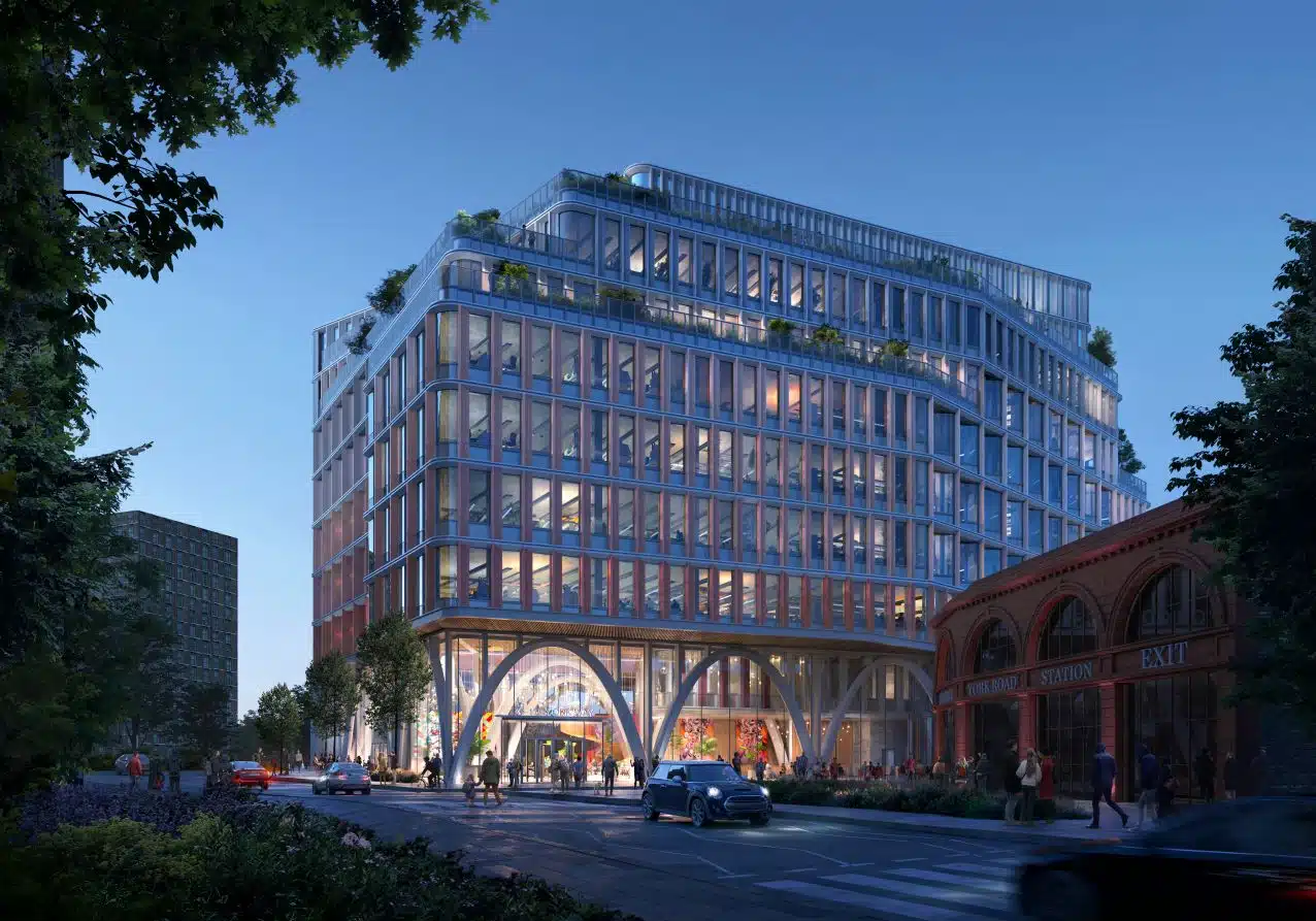
Harmonising structural design and architectural vision with advanced computational design – 176-178 York Way
Structural engineering
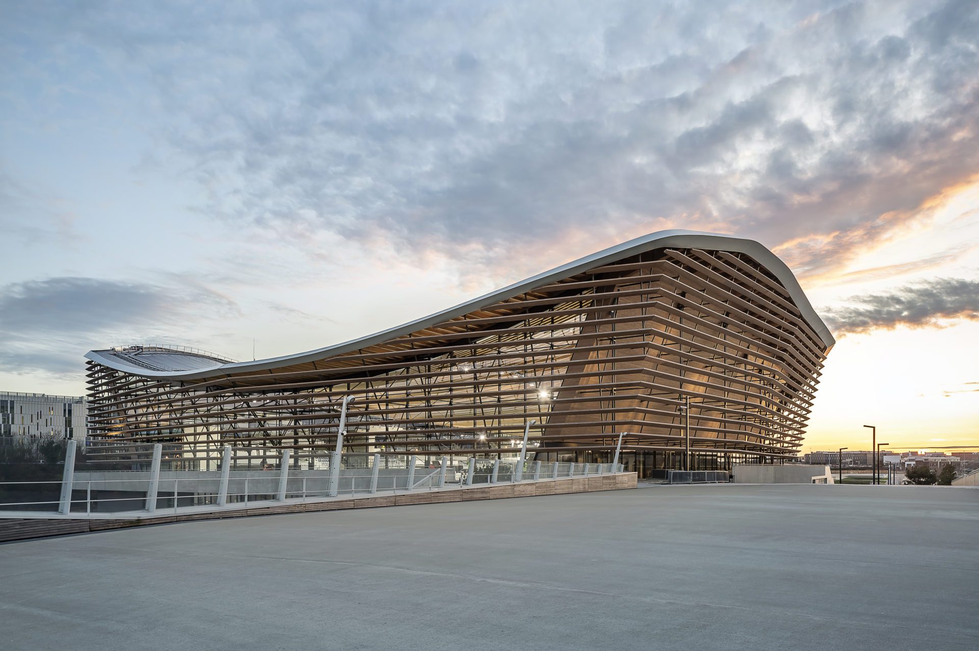
Ambitious technical innovations for sustainable design: Olympic Aquatics Centre, Paris 2024
Geotechnical engineering
Asset damage assessment in linear infrastructure projects – focus on utilities using Oasys XDisp
Structural engineering
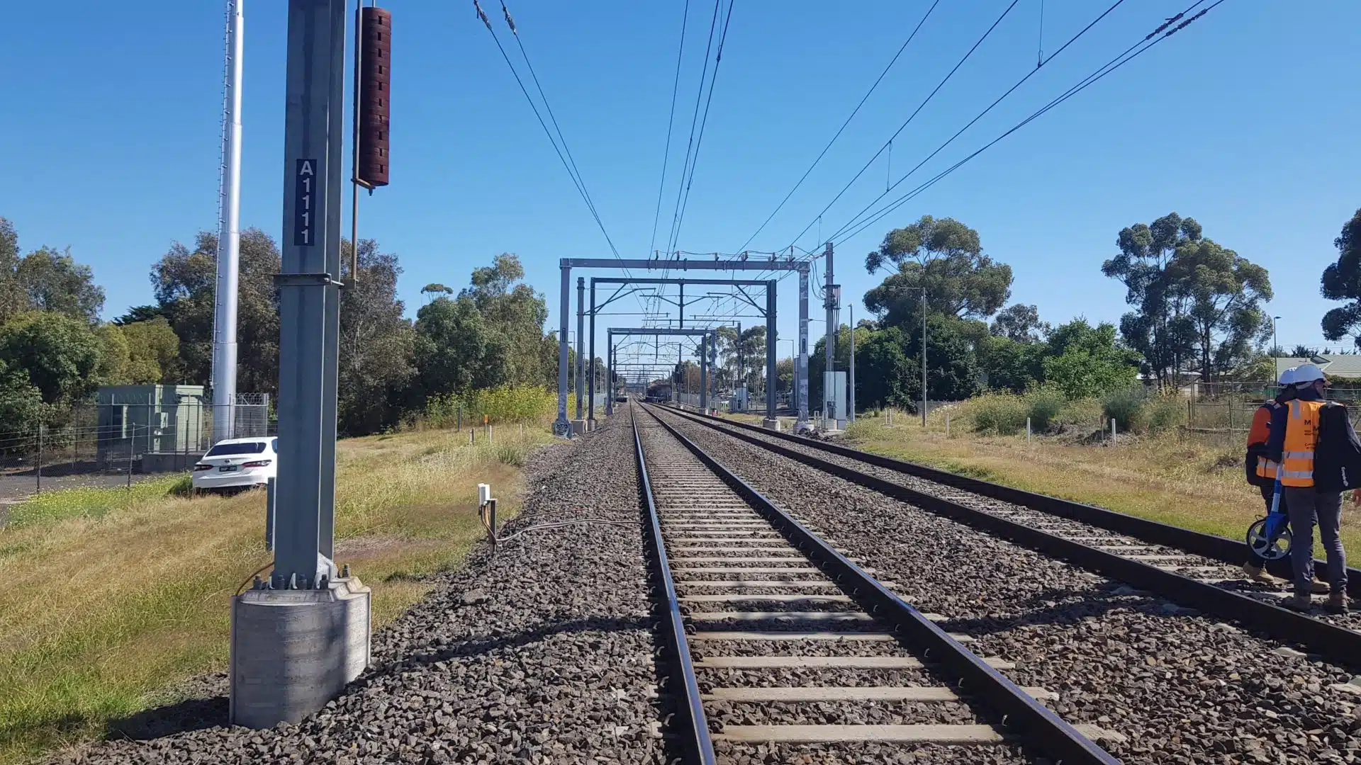
Seamless software integration drives efficiency for the Haymarket Edinburgh project
Geotechnical engineering
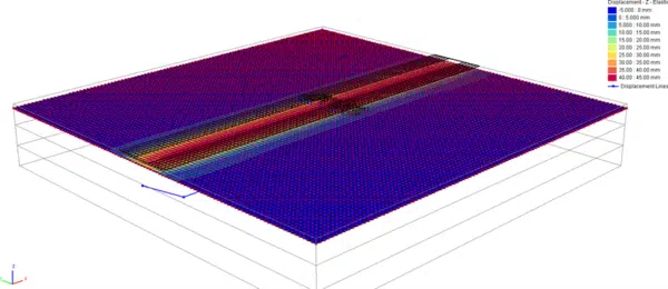
Ground movement assessment and settlement analysis with Oasys PDisp
Geotechnical engineering
Stabilising urban developments with Oasys XDisp and Oasys PDisp
Geotechnical engineering
Geotechnical design optimisation with Oasys Alp: Melbourne’s infrastructure project
Pedestrian simulation
Innovative use of Oasys MassMotion at Brunel University London
Structural engineering
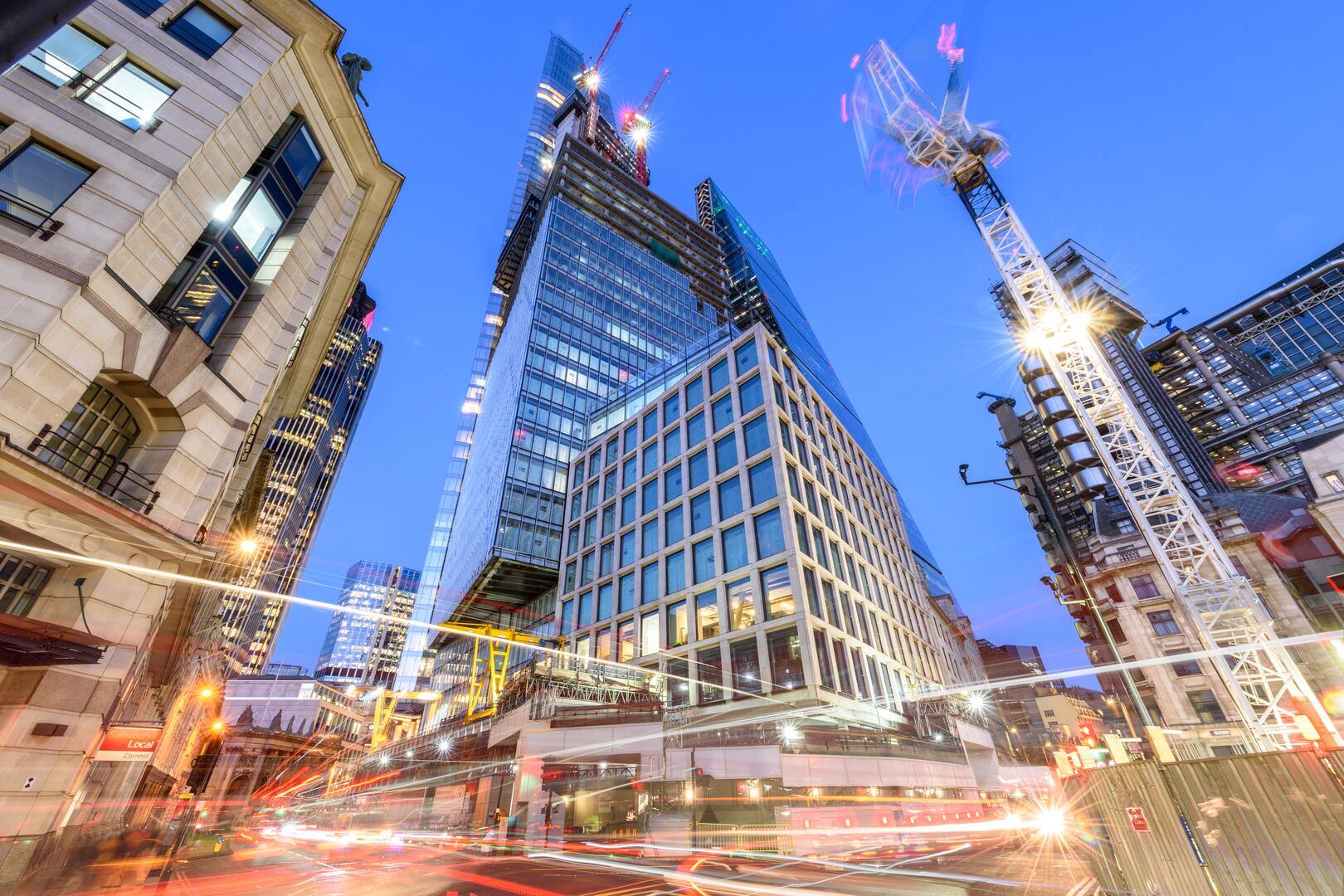
Powerful structural design and analysis of 8 Bishopsgate, London
Geotechnical engineering
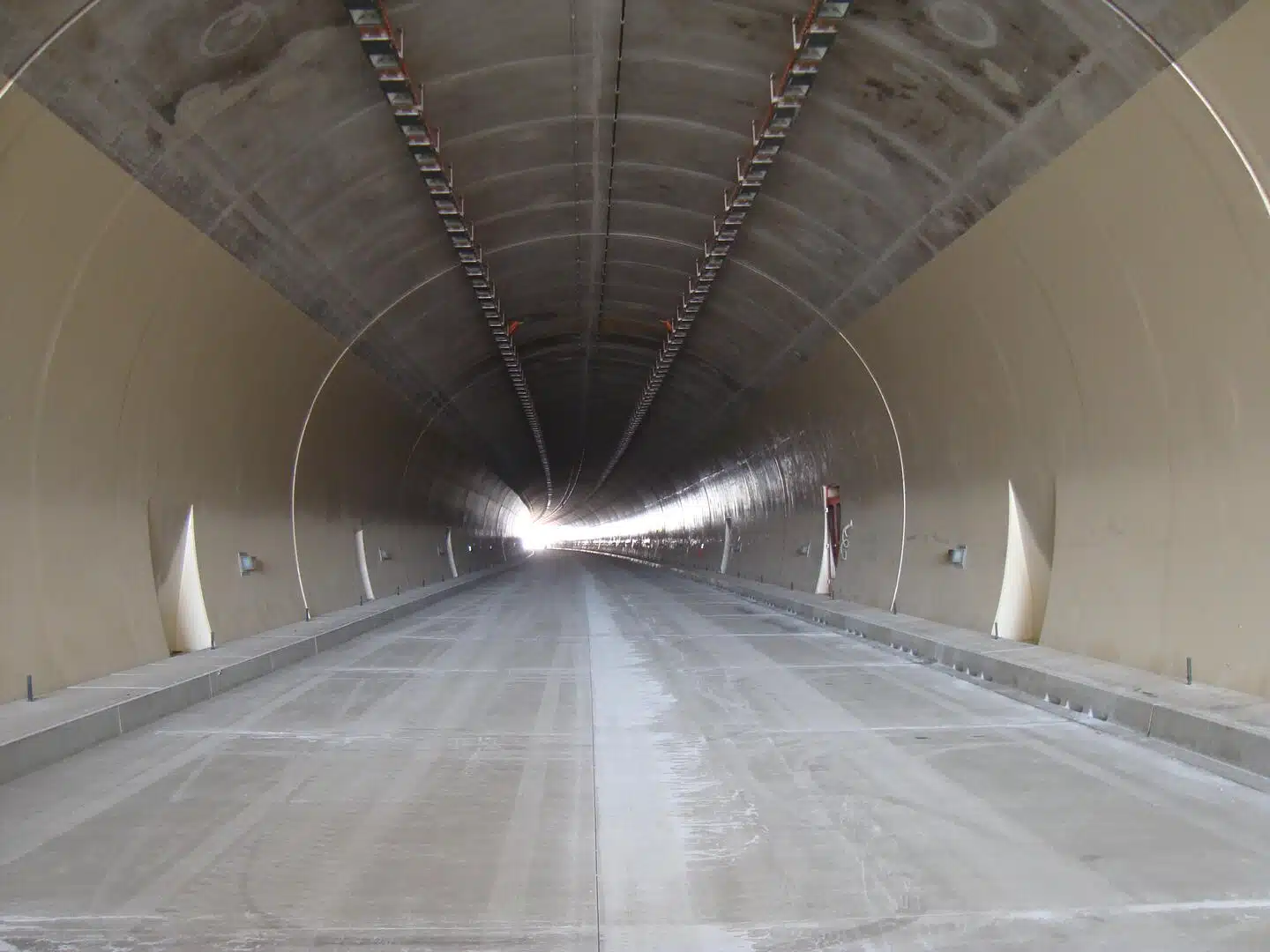
Automating tunnel-induced impact assessment design with Oasys XDisp
Structural engineering
Intricate structural analysis of Reciprocal Frames using Oasys GSA
Structural engineering
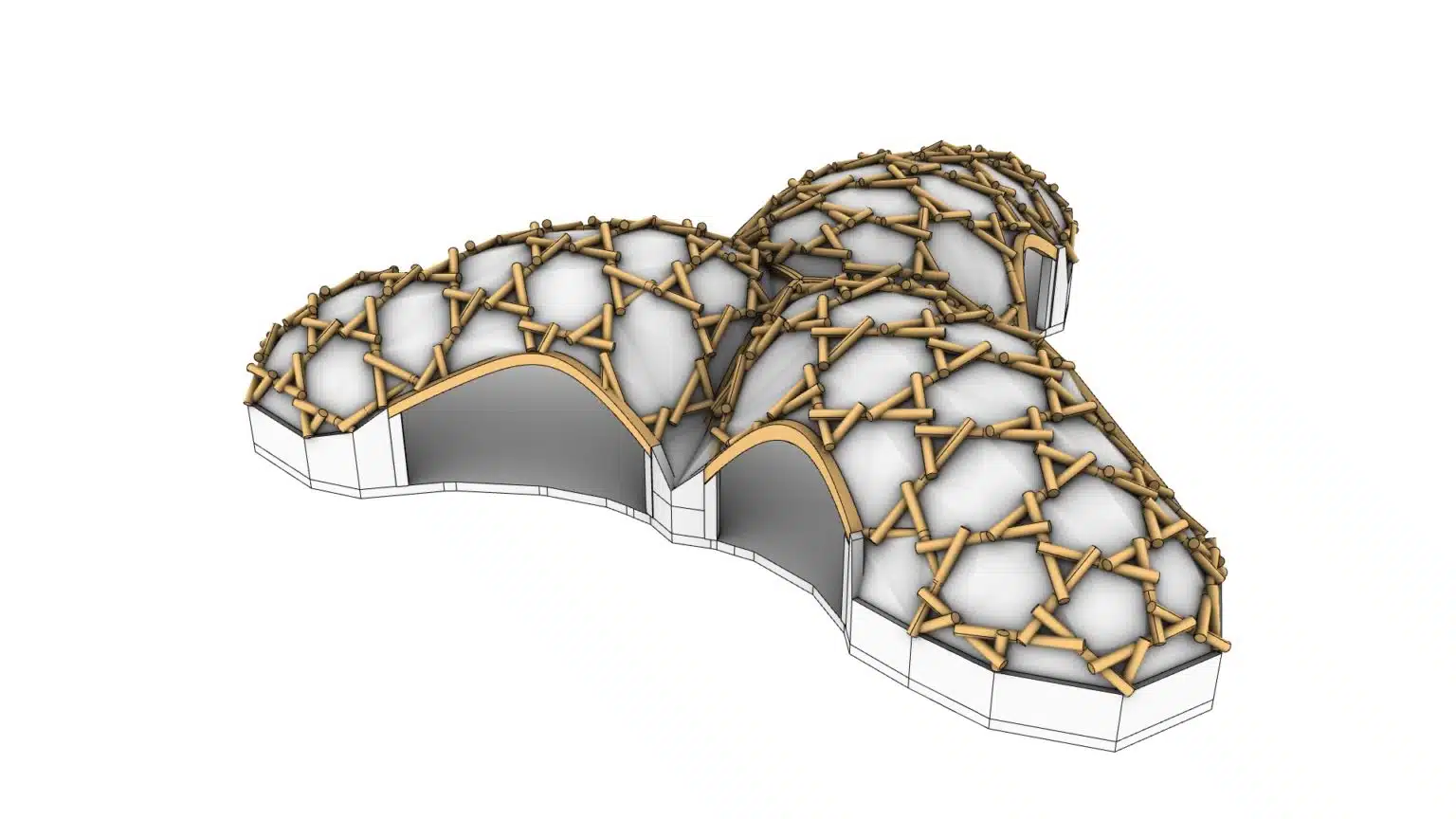
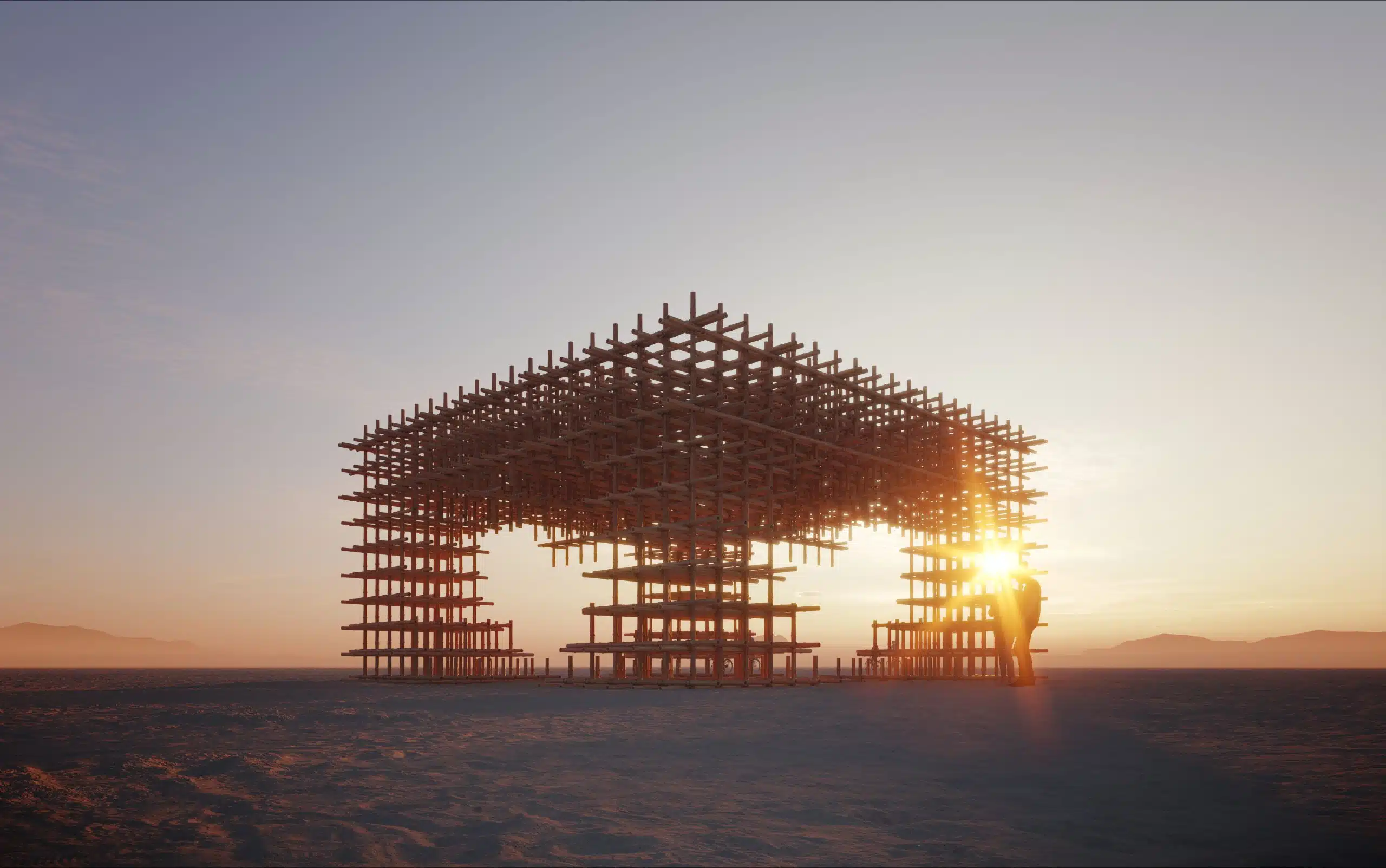
Structural analysis and design of a bamboo art installation using Oasys GSA
Structural engineering
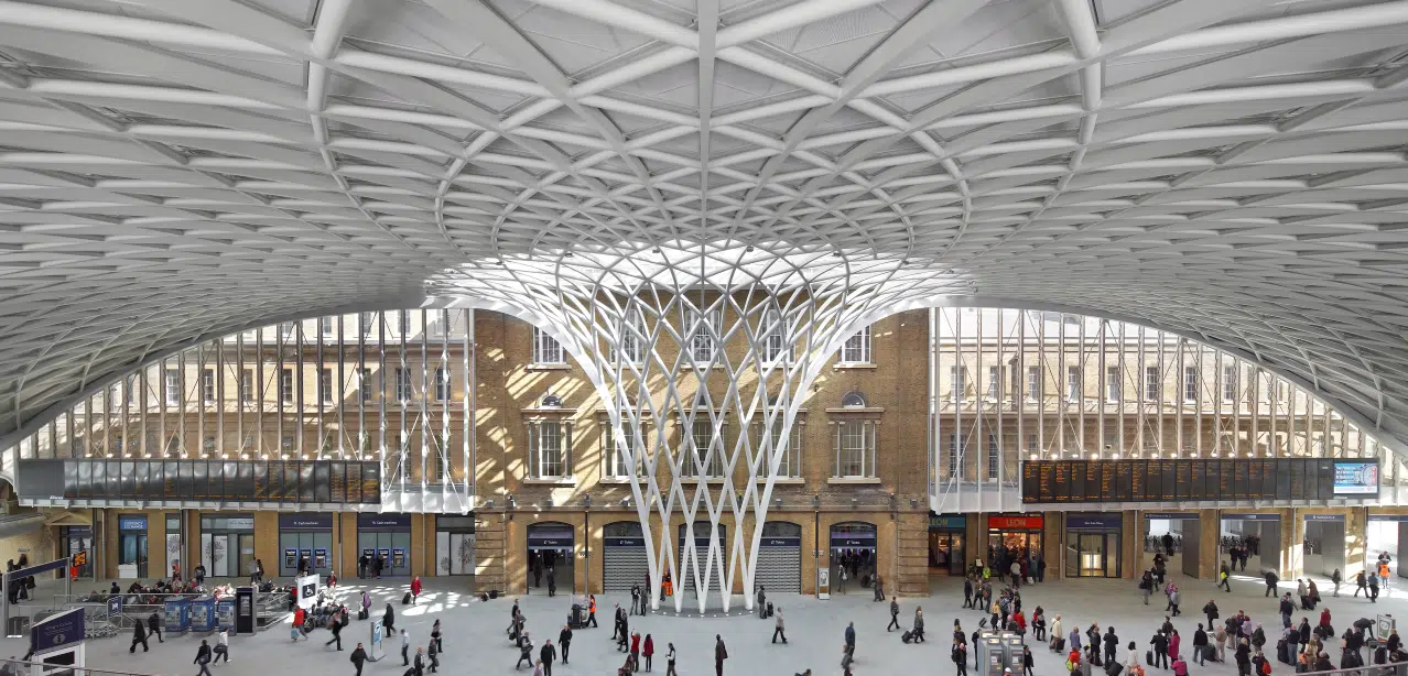
King’s Cross station redevelopment – roof analysis and design using Oasys GSA
Structural engineering
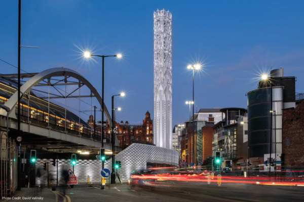
Tower of Light, Manchester, UK – Complex modelling using Oasys GSA
Structural engineering
Evacuation modelling of Cendana apartment building, Guatemala City using Oasys MassMotion
Structural engineering
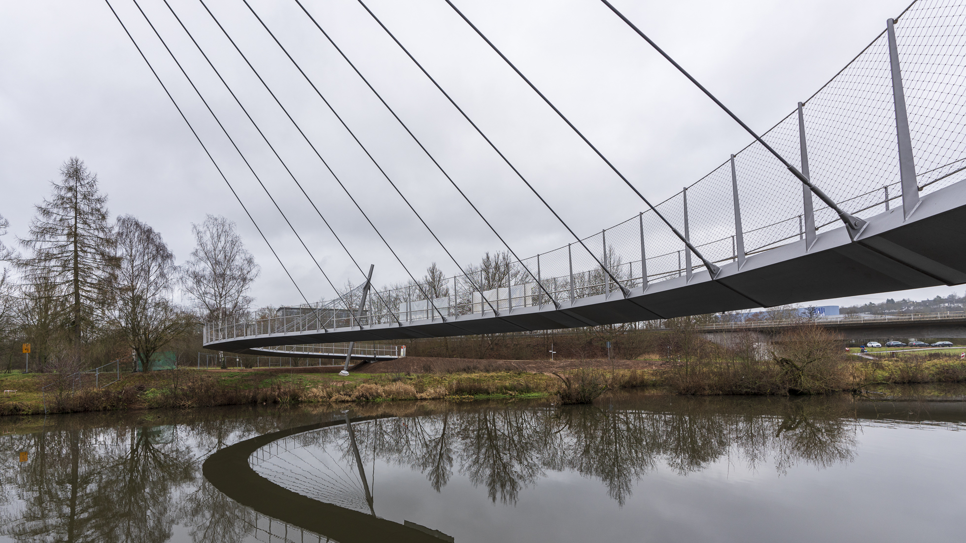
Structural design and dynamic assessment of an asymmetric cable-stayed footbridge
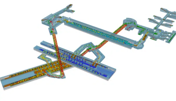
Pedestrian simulation
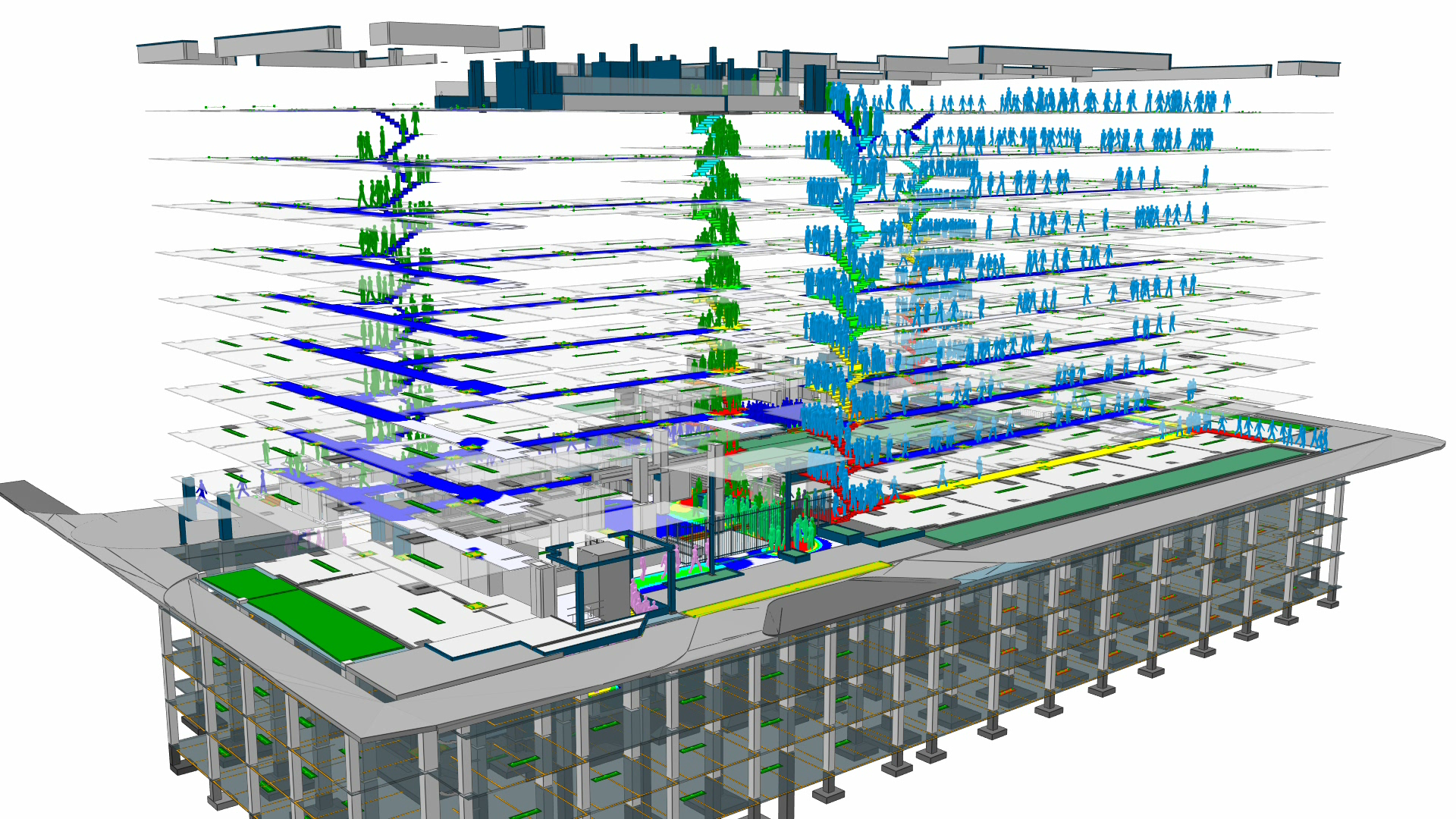
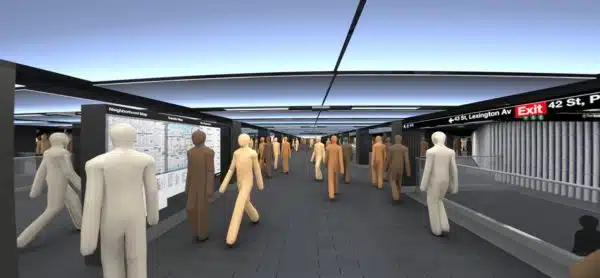
Future performance assessment of Grand Central Station-42nd Street Subway, New York City using Oasys MassMotion
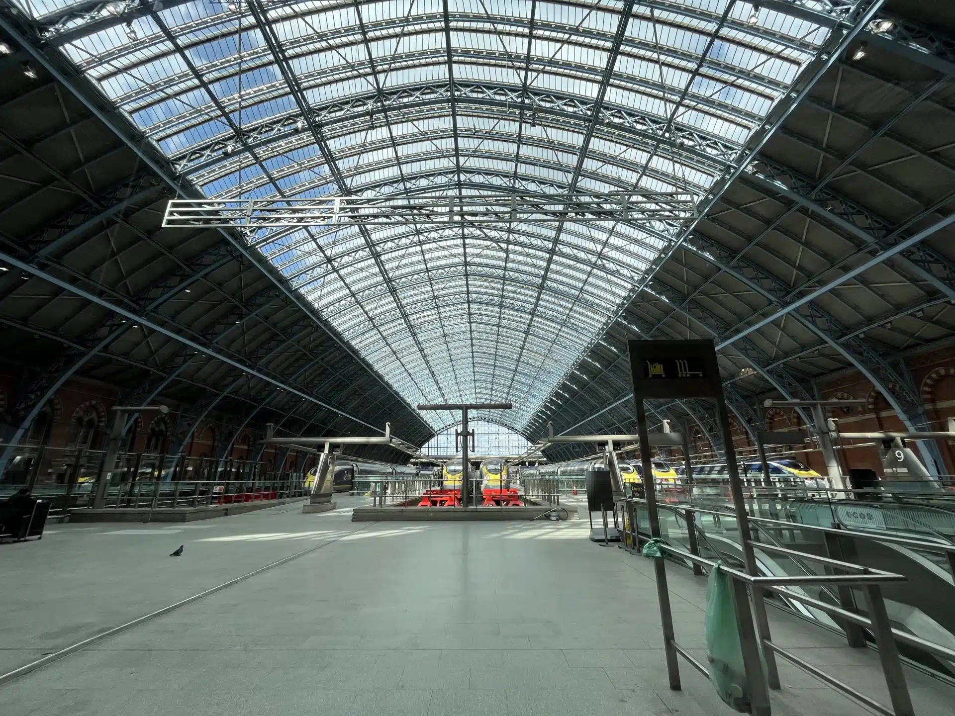
Structural engineering
Structural assessment of the Barlow train shed, London St. Pancras International using Oasys GSA
Pedestrian simulation
The use of reality capture technology to develop pedestrian models using Oasys MassMotion
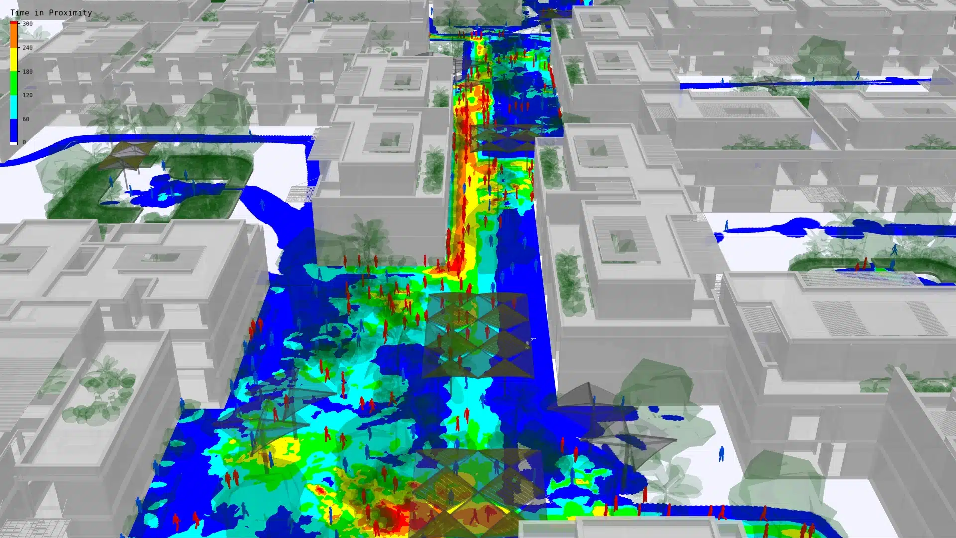
Pedestrian simulation
Proximity analysis for South Sabah Al-Ahmad masterplan: A Foster + Partners project
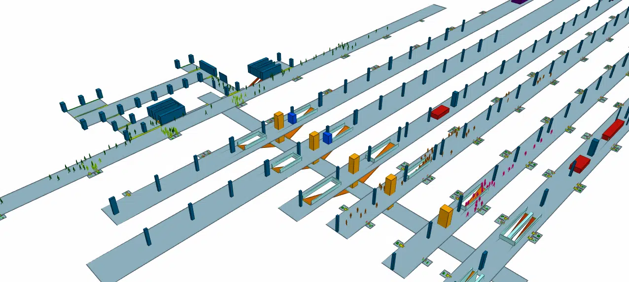
Pedestrian simulation
Optimisation of pedestrian transit spaces: Railway station in Rome, Italy
Pedestrian simulation
Simulating pedestrian vision and wayfinding with Oasys MassMotion
Pedestrian simulation
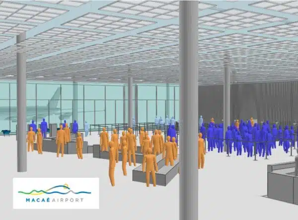
Improving passenger experience at Macaé Airport, Brazil with Oasys MassMotion
Pedestrian simulation
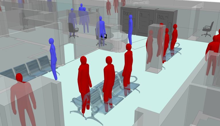
Whittington Emergency Department capacity modelling using Oasys MassMotion
Structural engineering
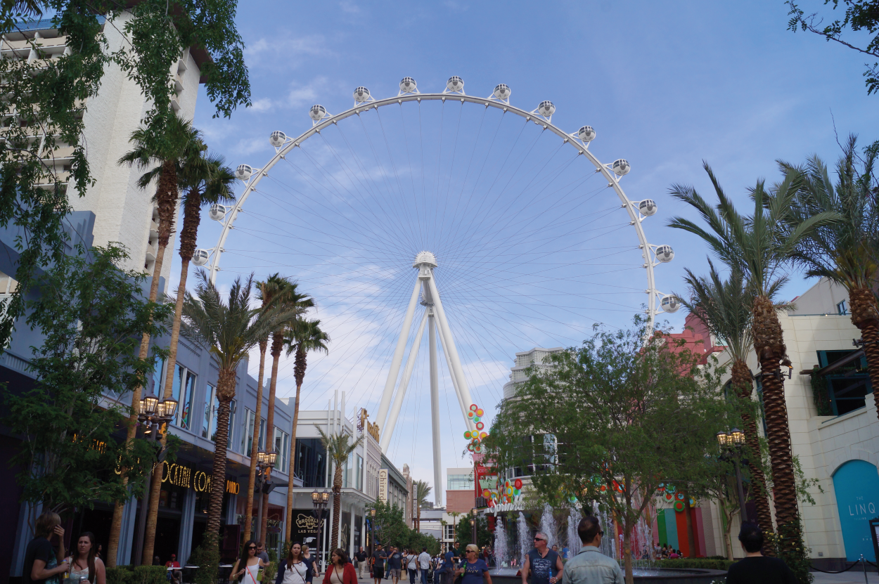
Intricate analysis and design of Las Vegas High Roller observation wheel
Pedestrian simulation
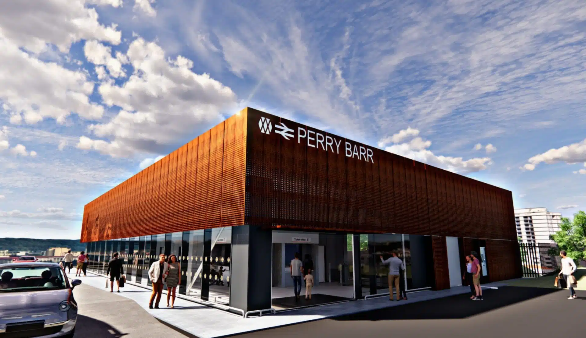
Station modelling: Major redevelopment of Perry Barr Station, Birmingham
Structural engineering
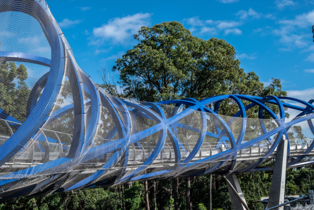
Sydney’s double helix bridge at Lachlan’s Line
Structural engineering
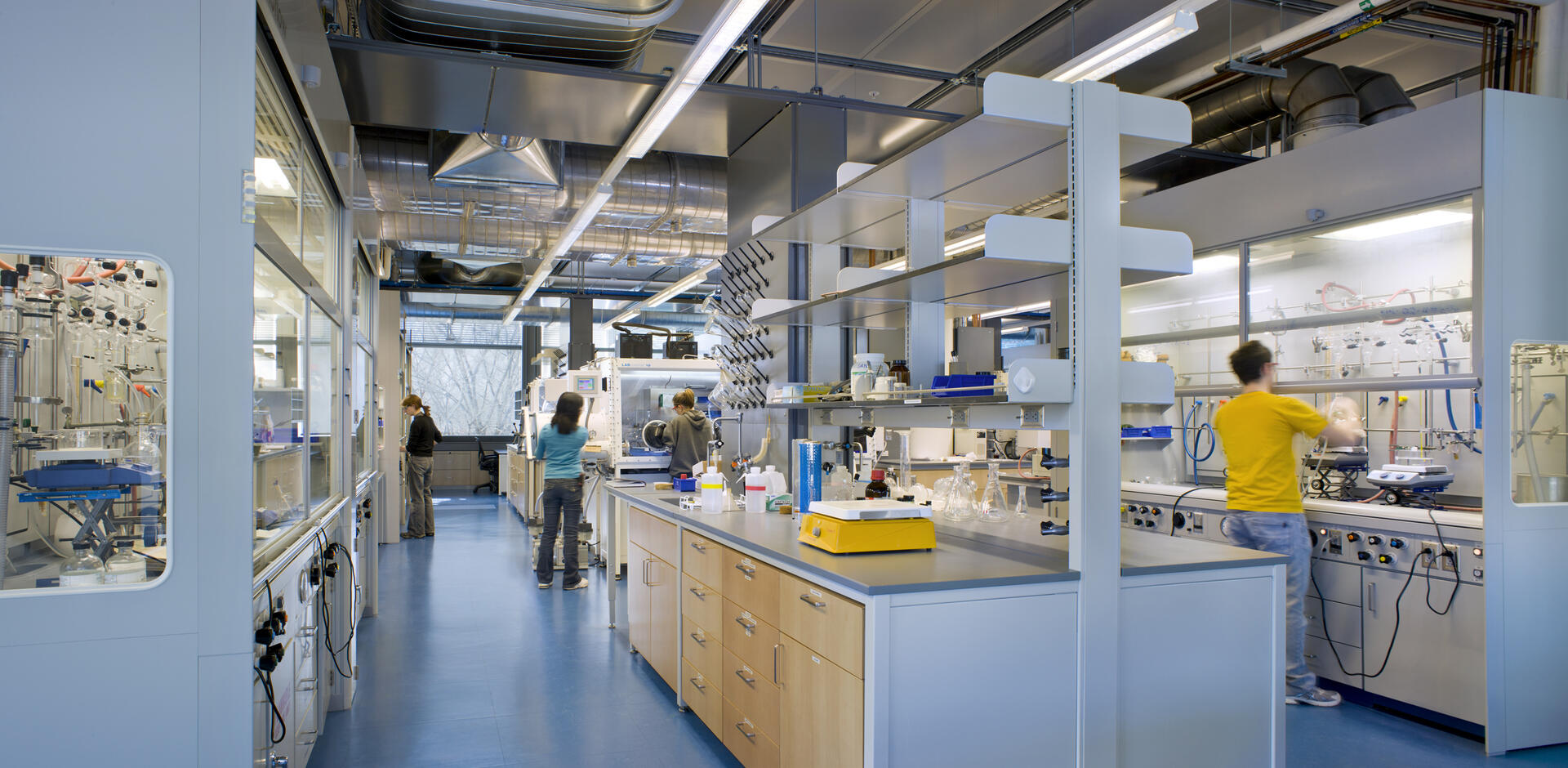
Princeton University, frick laboratory
Structural engineering
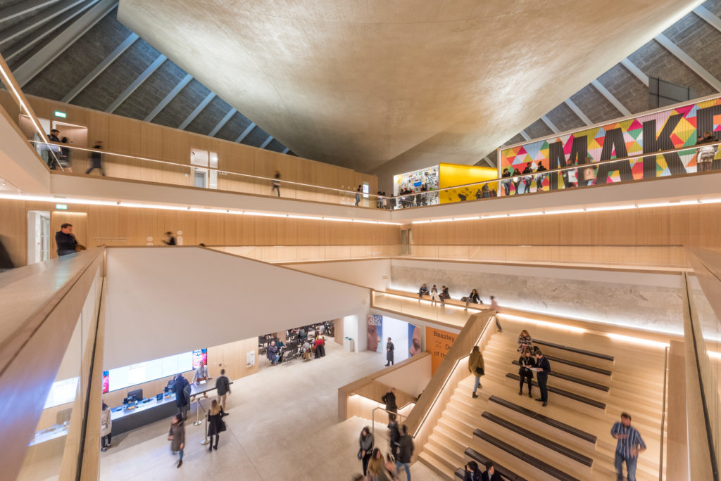
Design Museum, London
Structural engineering
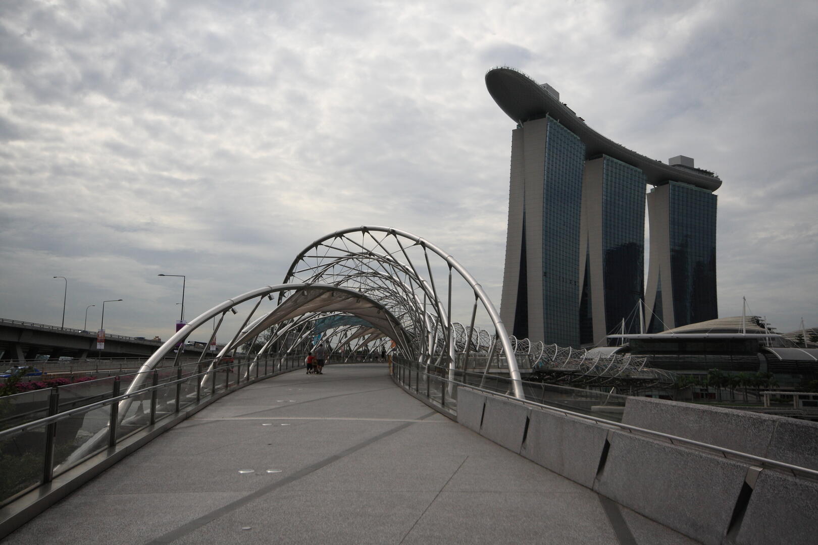
Footfall analysis for Singapore’s Helix Bridge
Pedestrian simulation
Improving passenger flow at Beijing Daxing International Airport
Structural engineering
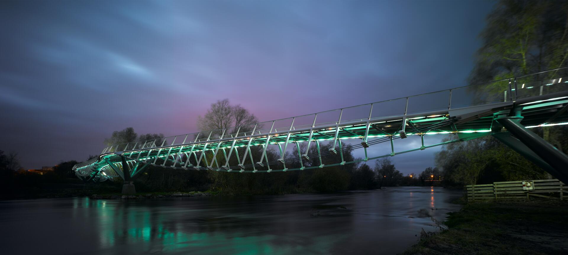
Living Bridge, University of Limerick
Pedestrian simulation
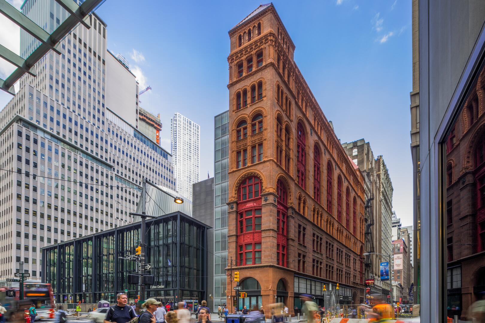
New York’s Fulton Center
Structural engineering
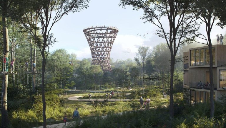
Structural design and analysis of hyperboloid lattice tower
Trusted by over 6,000 users on a range of projects across the globe


Calling Oasys community!
Got a case study about using Oasys software to share? Get in touch – we’d love to help you share your success stories.