Software Used on this Project
Project Overview
Requirements
Following the construction of cut and cover tunnel sections, concerns were raised by the Client about drainage pipes cast into the base slab of the cut and cover tunnel segments. Various additional justification calculations have been carried out by the contractor but there had been no resolution of the issue. Consequently, additional analyses were proposed based on more rigorous methods.
Raison Foster Associates were asked by the contractor to investigate the stresses within the tunnel section base slab for a cut and cover tunnel.
The project is confidential in nature and, as such, the location and specifics of the project has not been included but, the analysis methods and outcome of analysis will be discussed.
Constraints
Drainage pipes have been cast into the base slab and the client wanted to understand the stresses on these pipes. Consequently, the client required more rigorous analysis using finite element analysis (FEA) methods.
How Oasys proved invaluable
Analysis
To carry out the FEA check, Raison Foster used Oasys SAFEt (Version 19.0). This program is designed to carry out finite element computations for a wide range of geotechnical situations. The program computes soil stresses, strains and deformations through one more sequences of events allowing staged construction to be considered directly. Time dependent consolidation and steady state seepage can also be modelled. The program provides displacements, total and effective stresses, strains and pore water pressures as either tabulated or plotted output.
Geometry
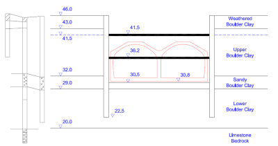
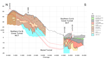
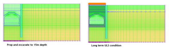
A section that was representative of the deeper cut and cover tunnels was chosen for the analysis, The section has been prepared on the basis of as built drawings and a review of the local site investigation boreholes. For the SAFE analyses, a half section has been adopted as shown for an axisymmetric analyses. At this location the excavation is approximately 23m wide with parallel 1.2m wide diaphragm walls providing the temporary works support with or two levels of 1320mm diameter tubular steel props. Excavation at this chainage was taken to 15.5m depth prior to construction of the reinforced concrete tunnel section and backfilling.
Materials and Soil Modelling
Although a range of material models are available, this analysis used the linear elastic model for the structural elements (tunnel segments, diaphragm wall, temporary props e.t.c.) and the elastic Mohr-Coulomb model for the different soils.
The soil stratigraphy along the tunnel is shown below.
The analyses are intended to investigate most probable behaviour under service conditions with final stages to represent service limit (SLS) and ultimate limit (ULS) conditions. Soil design parameters are therefore unfactored for all stages of the analysis. Both drained and undrained soil behaviour was modelled.
Construction Sequence
0. Initial conditions
1. Install diaphragm wall and excavate to 5m depth
2. Prop and excavation to 10.5m depth with dewatering
3. Prop and excavation to 15.5m depth with dewatering
4. Construction and delay at formation level with dewatering
5. Place drainage layer and cast tunnel base slab
6. Remove lower prop
7. Complete tunnel segments
8. Backfill above tunnel to underside of upper prop
9. Remove upper prop
10. Backfill above tunnel to ground level
11. Construct road formation inside tunnel
12. SLS long term conditions
13. ULS long term conditions
Alternate analyses have been carried out assuming a construction delay (Event 4) sufficient to allow fully drained behaviour and full dissipation of negative pore water pressures following completion of the excavation.
Results
It was possible to compare the maximum computed bending moment taken from the various SAFE output for comparison with the ultimate bending moment capacity and cracking moment for the diaphragm wall. In all cases the margin between the ultimate bending moment capacity and computed values is sufficient to ensure adequate king term durability and performance of the diaphragm walls. This will ensure any long term support provided by the retaining walls is likely to remain for the design life of the tunnel.
SAFE computed deflections for the tunnel base slab were also reviewed. Net movements were reviewed for the period between casting the base slab and the long term SLS case.
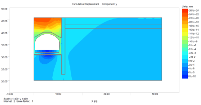
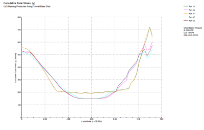
Additional outputs were extracted from the SAFE computations to investigate the likely bearing pressures between the tunnel base slab and the underlying ground. Plotted output for the SLS and ULS analysis stages are shown. For both analysis cases, it is shown that the available bearing capacity exceeds the computed bearing pressure by a sufficient margin.
The drainage pipe in embedded in the base slab about 1.25m from the side of the wall. Maximum computed bending moments, shear force and thrust were extracted from the SAFE results to assess the capacity of the pipe.
Credits
Geotechnical Engineer: Raison Foster Associates