News
Stay up to date with the latest news from Oasys, including software releases, product updates, events, webinars, partnerships, and company announcements.

Oasys
A refreshed Oasys website built with you in mind
Posted April 28th 2026
Oasys
Celebrating half a century of software development
Posted April 16th 2026
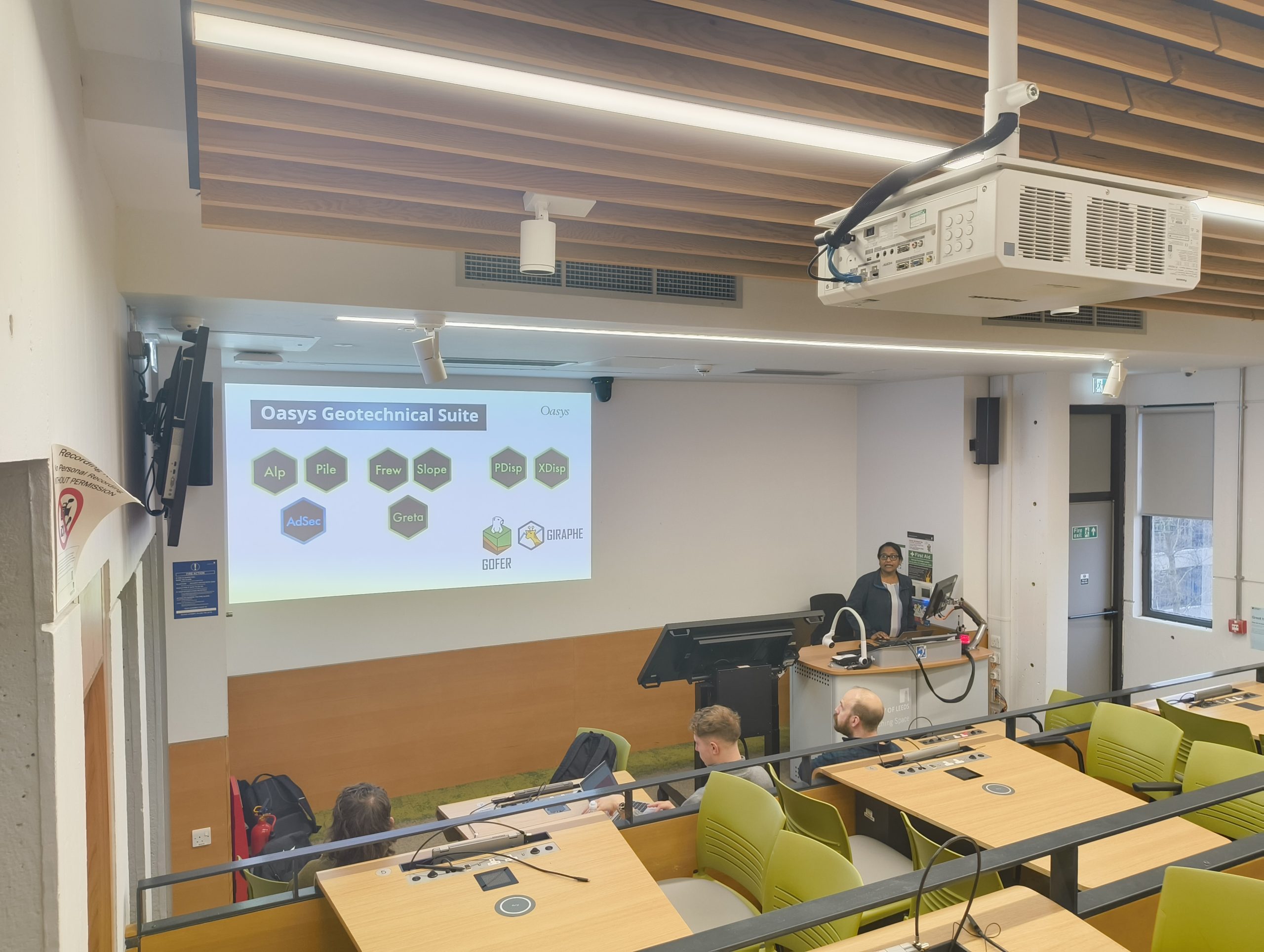
Geotechnical engineering
Bringing real‑world ground engineering to the University of Leeds
Posted March 27th 2026

Geotechnical engineering
Supporting the next generation of Geotechnical Engineers at the University of Birmingham
Posted March 4th 2026
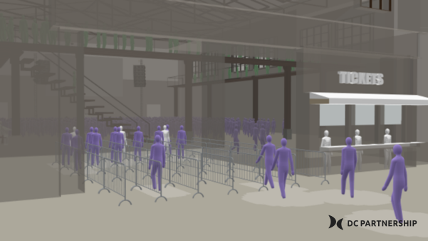
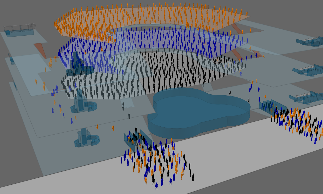
Pedestrian simulation
DC Partnership’s CrowdEx team levels up with Oasys MassMotion
Posted February 13th 2026
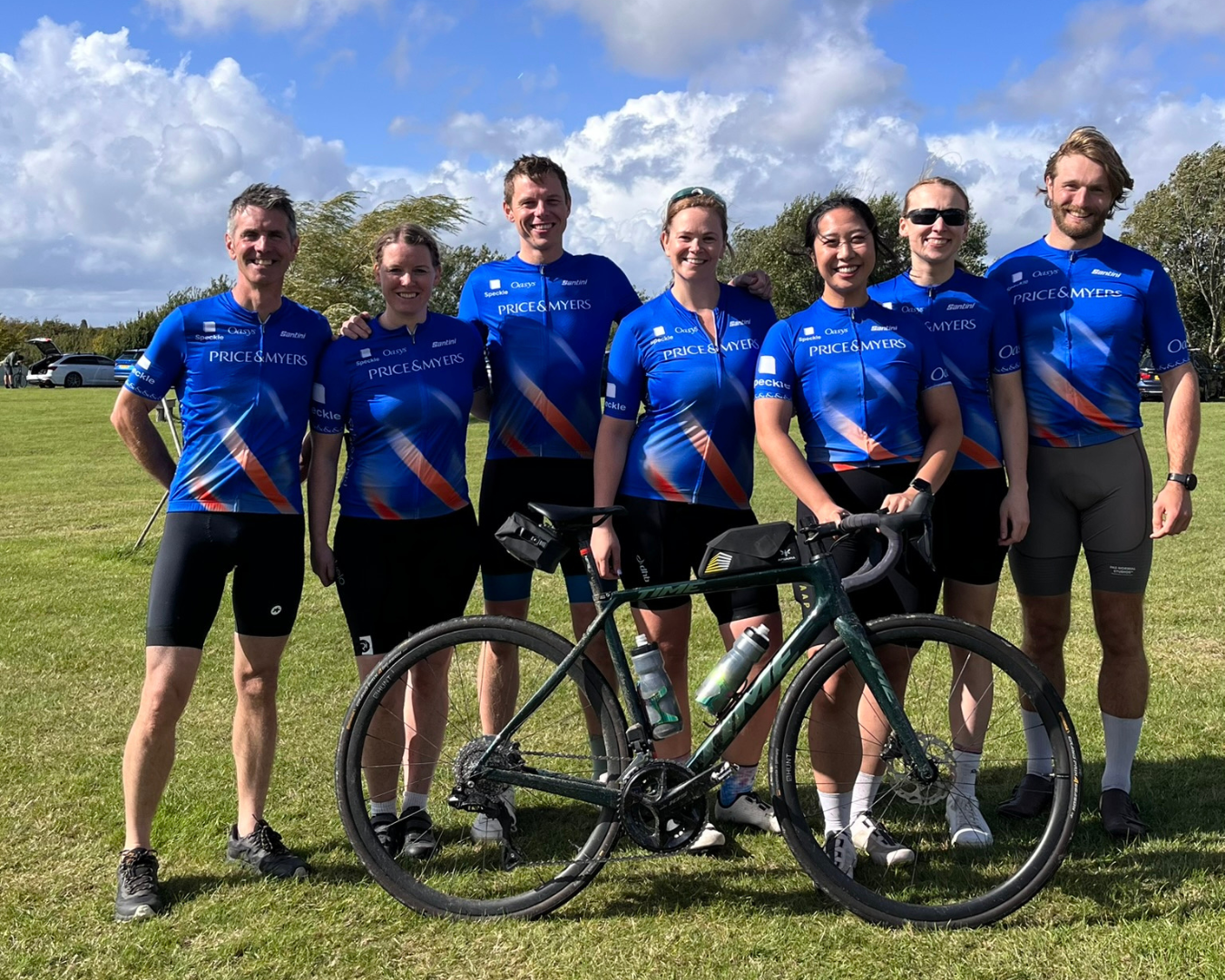
Oasys
Supporting our clients: Price & Myers cycling team
Posted November 7th 2025

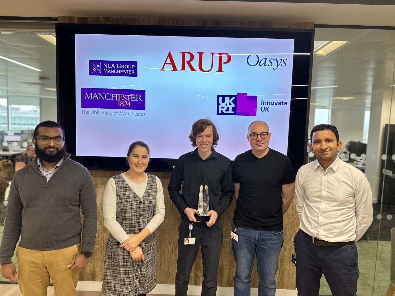
Structural engineering
Ground breaking algorithm in Oasys GSA wins Innovate UK Golden Award
Posted November 7th 2025
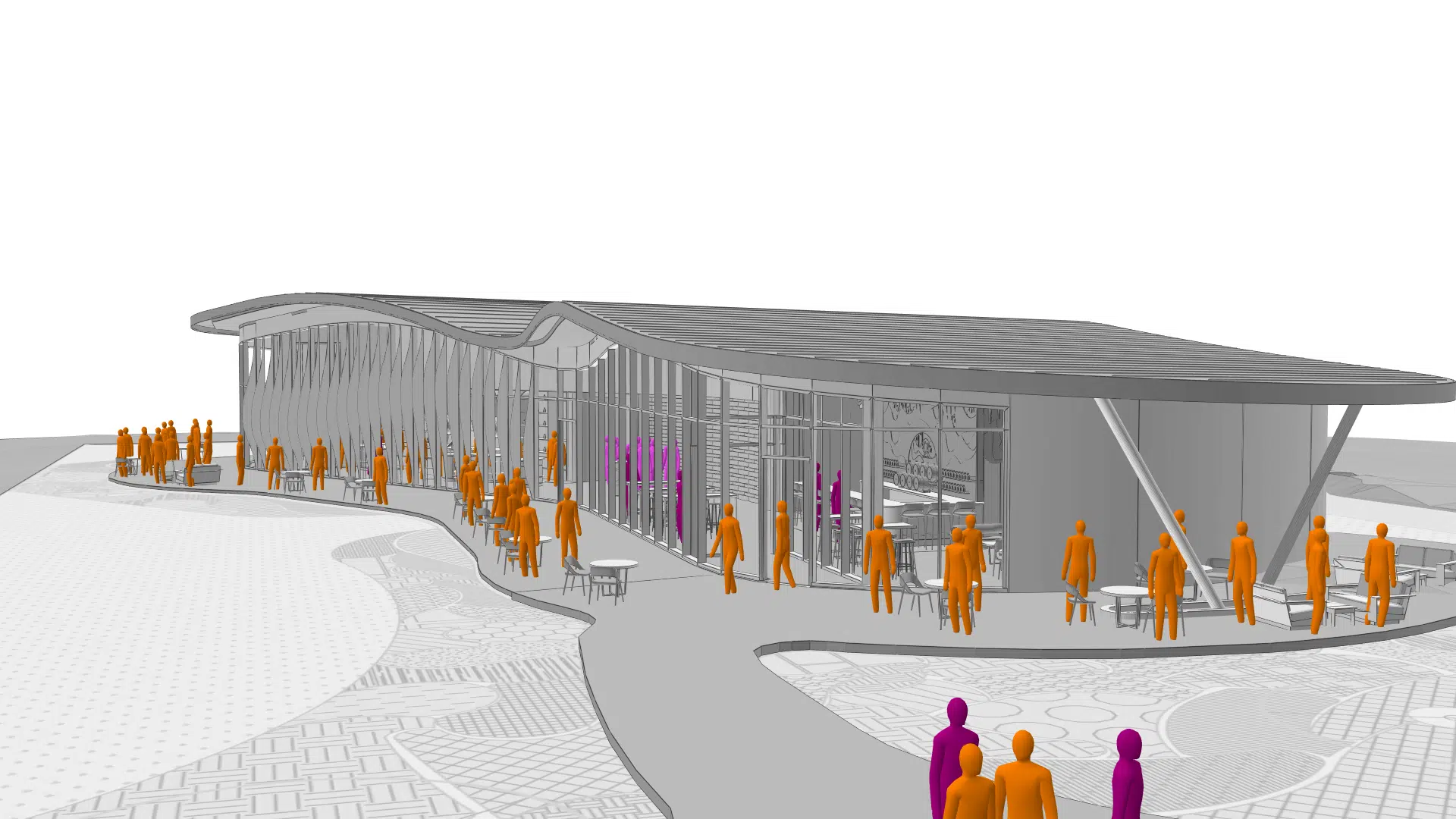
Pedestrian simulation
Shaping the future of pedestrian simulation with our champions
Posted June 2nd 2025
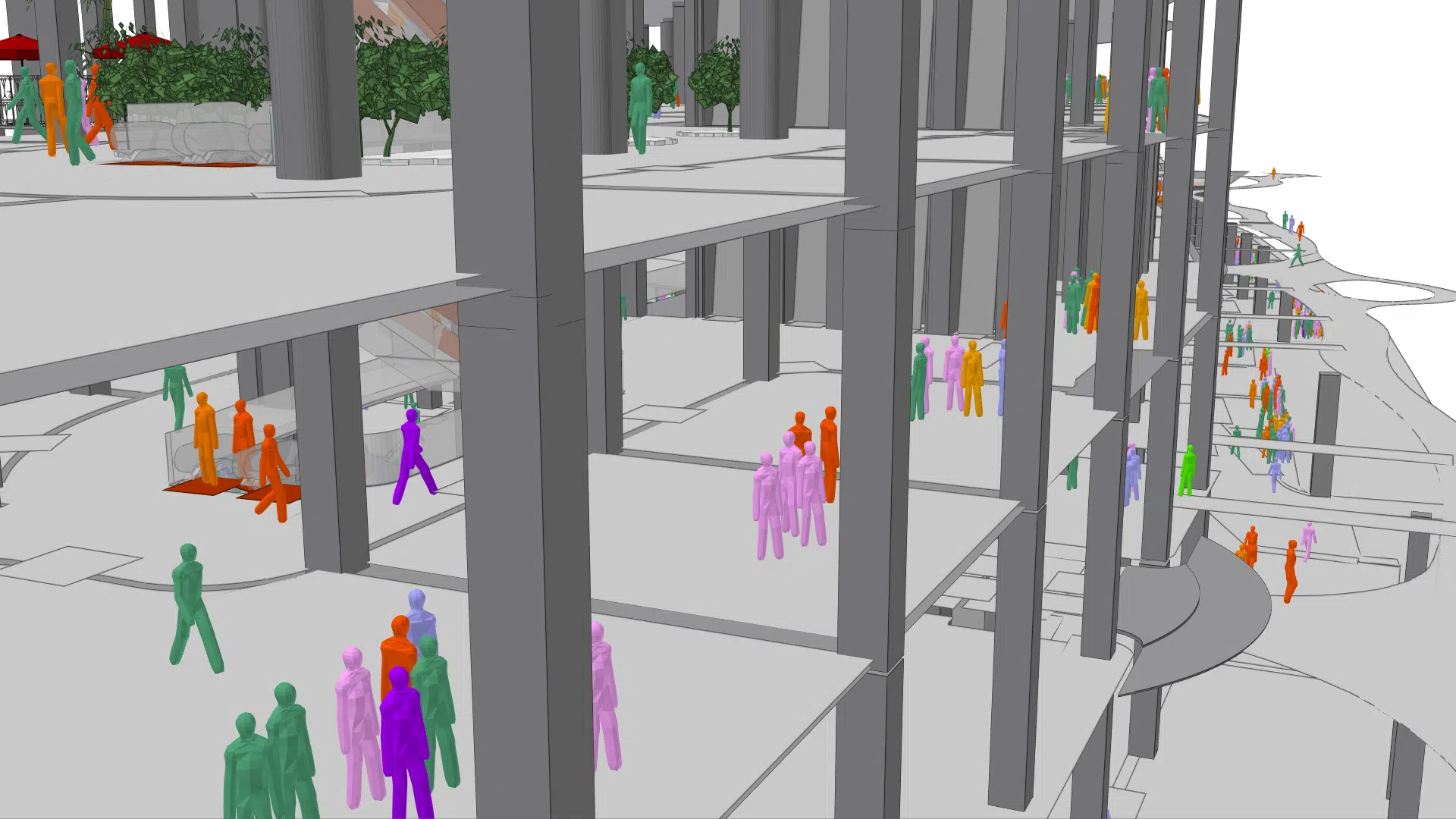
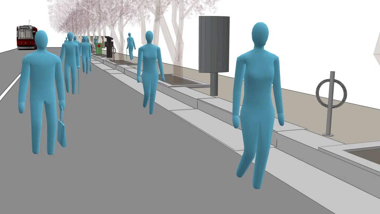
Pedestrian simulation
Synergising architectural research and crowd engineering
Posted April 3rd 2025
Oasys
Moving to ServiceNow: Oasys Customer Service Portal
Posted January 6th 2025

Geotechnical engineering
You asked, we listened: Discover dynamic graphing with Oasys Giraphe
Posted November 4th 2024

Pedestrian simulation
Taking Oasys MassMotion where it has never been taken before
Posted October 8th 2024
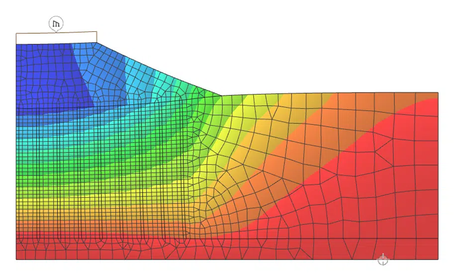
Geotechnical engineering
Unlock next level geotechnical analysis with Oasys Gofer
Posted September 20th 2024
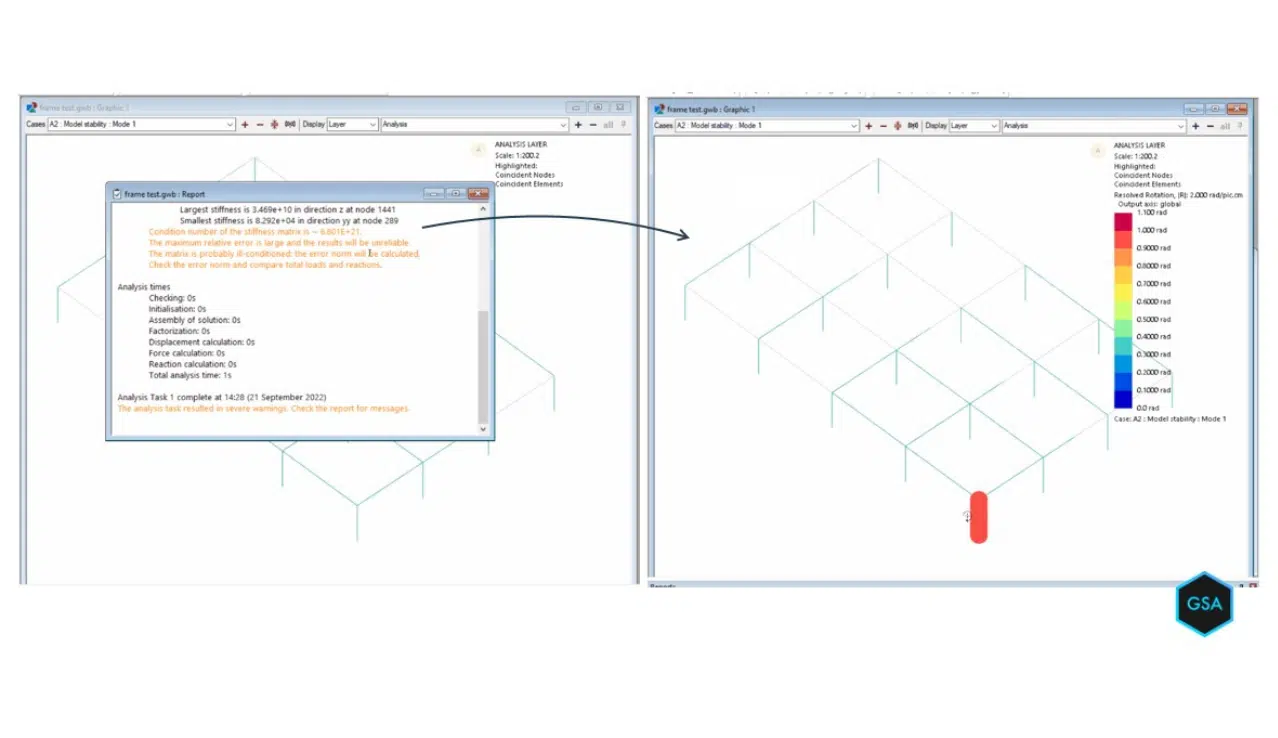
Structural engineering
Award-winning seismic analysis available in Oasys GSA
Posted July 24th 2024

Oasys
Team News: Oasys Marketing Manager, Sam Ross, achieves Chartered Marketer status
Posted July 10th 2024
Pedestrian simulation
Effortless model design and pedestrian simulation analysis
Posted May 19th 2024
Pedestrian simulation
Welcoming Oasys MassMotion advocates Lamar Johnson Collaborative (LJC)
Posted April 19th 2024
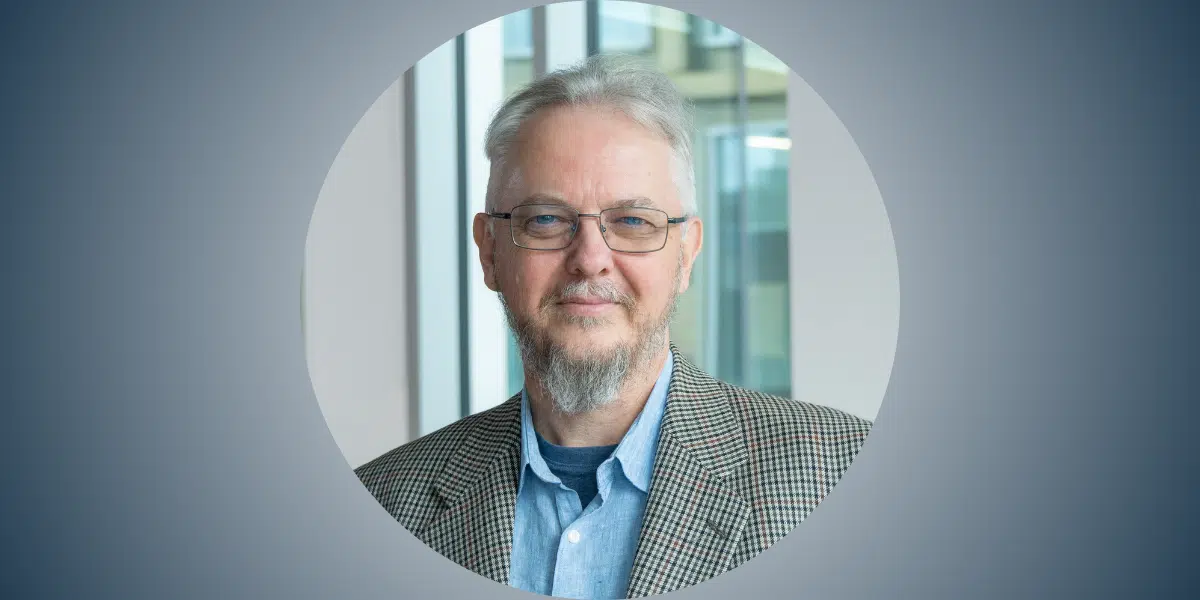
Oasys
Peter Debney appointed as Chair of the IStructE Yorkshire Regional Group (2024)
Posted January 15th 2024
Structural engineering
Arup and University of Manchester win Innovate UK Technical Excellence Award
Posted December 20th 2023

Geotechnical engineering
One year of Oasys Gofer
Posted October 10th 2023
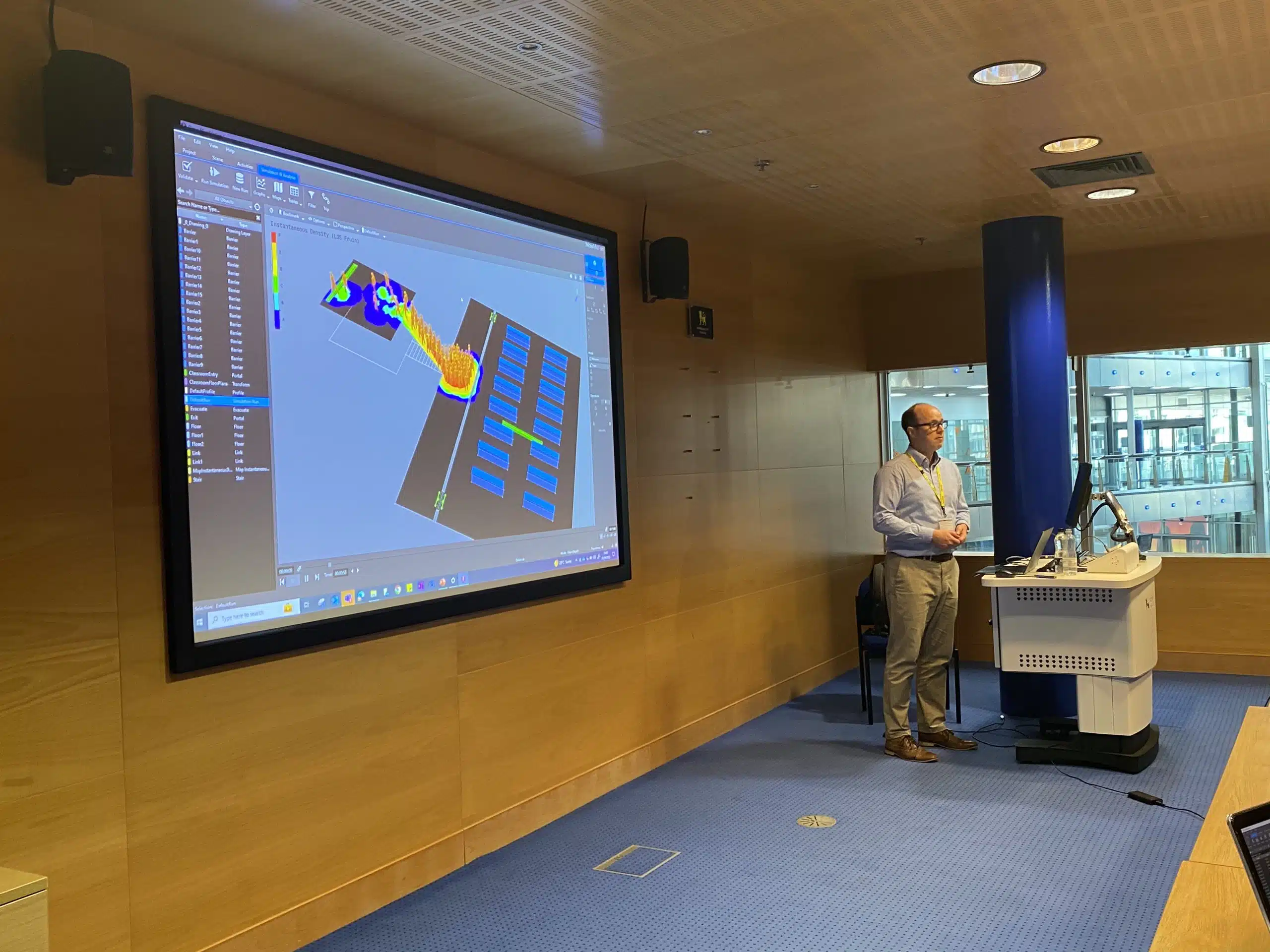
Pedestrian simulation
Human behaviour in fire guest lecture with Oasys MassMotion
Posted September 15th 2023

Geotechnical engineering
Oasys Gofer: Features and updates
Posted May 16th 2023
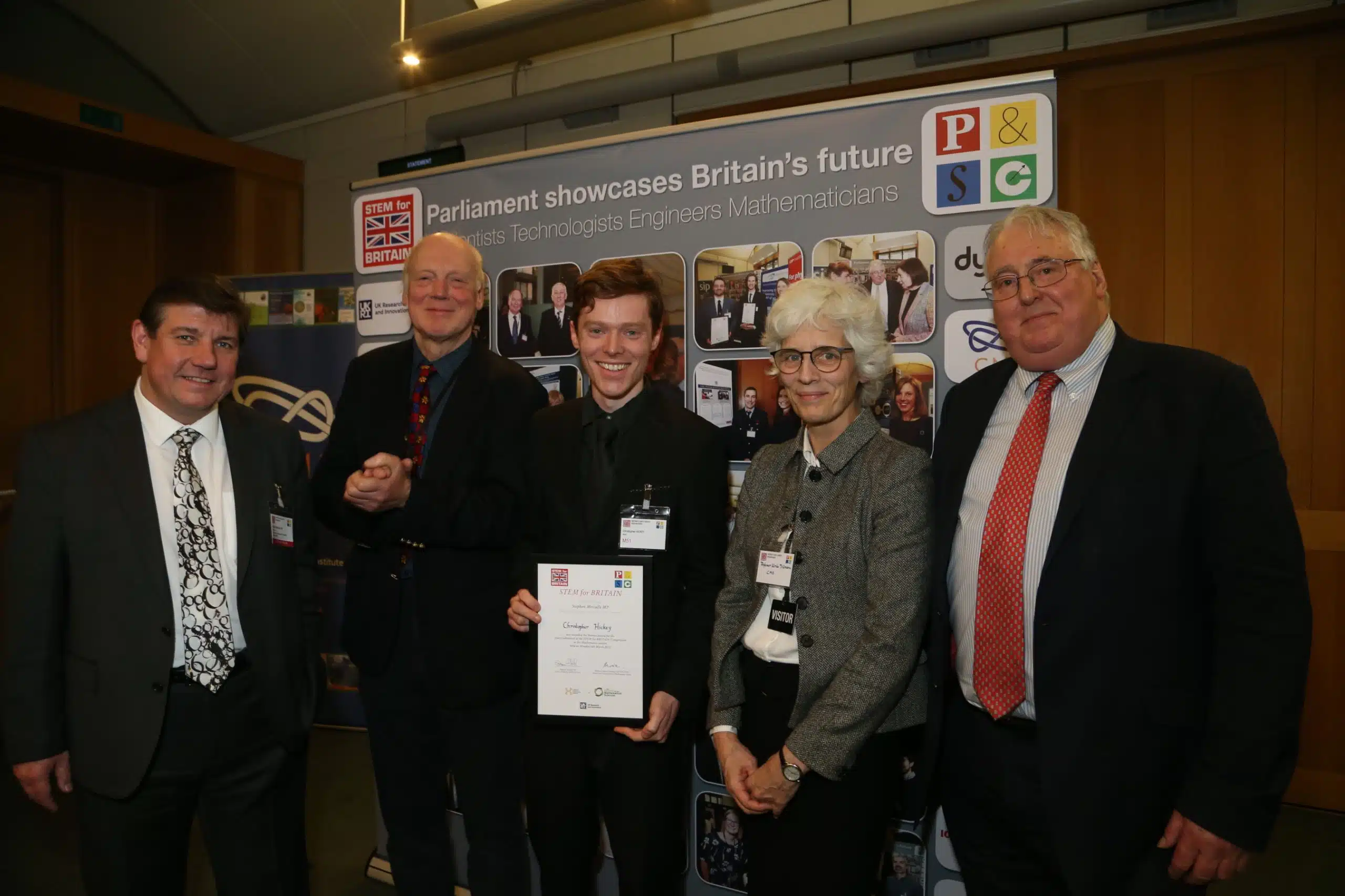
Oasys
Chris Hickey wins bronze medal at The Parliamentary & Scientific Committee’s STEM for BRITAIN 2023
Posted May 10th 2023
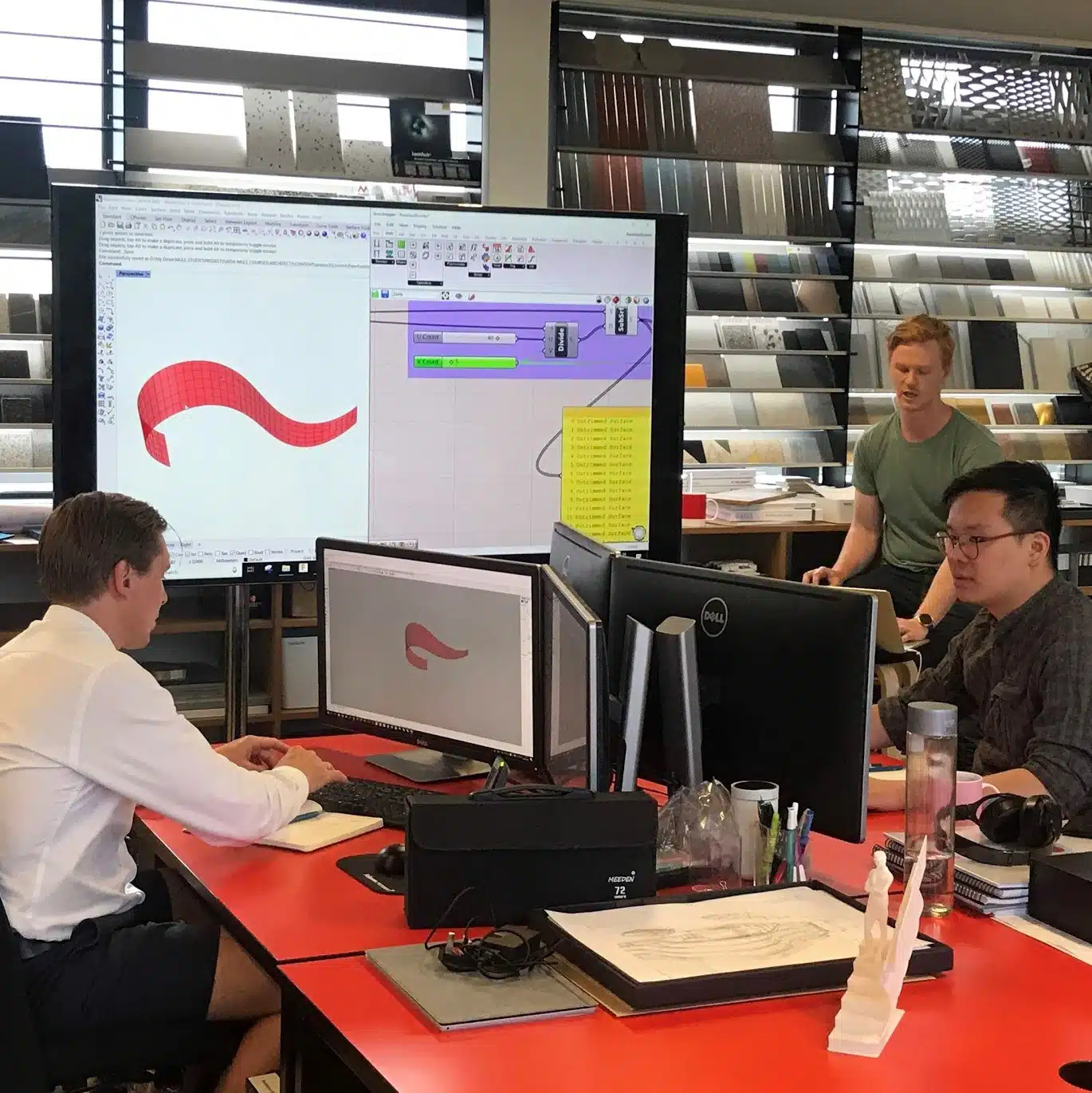
Structural engineering
Mule Studio parametric design and automation course using Oasys GSA-Grasshopper Plugin
Posted March 30th 2023
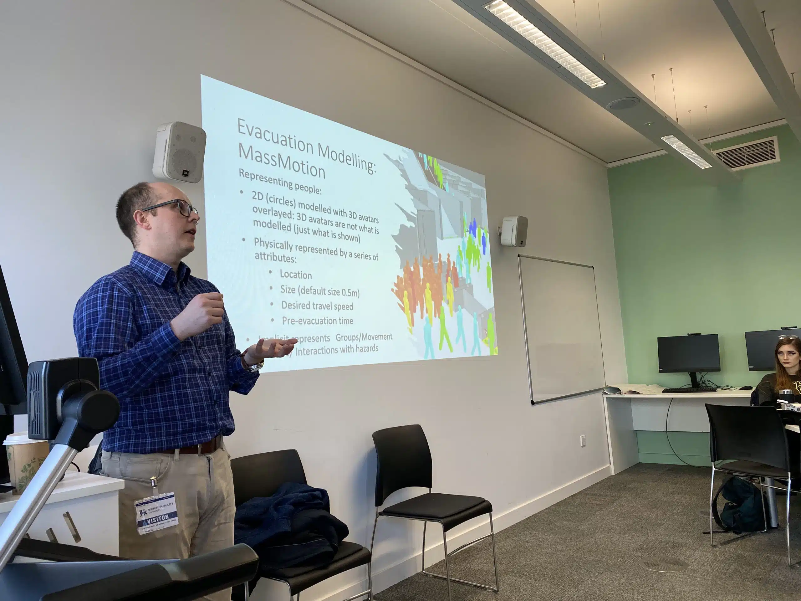
Pedestrian simulation
Human behaviour in fire guest lecture featuring Oasys MassMotion at Birmingham City University
Posted March 21st 2023
Pedestrian simulation
Oasys MassMotion: Arup digital transformation award winner
Posted January 4th 2023

Geotechnical engineering
Meet Oasys Gofer
Posted October 10th 2022

Pedestrian simulation
Building Innovation Awards 2022
Posted October 6th 2022
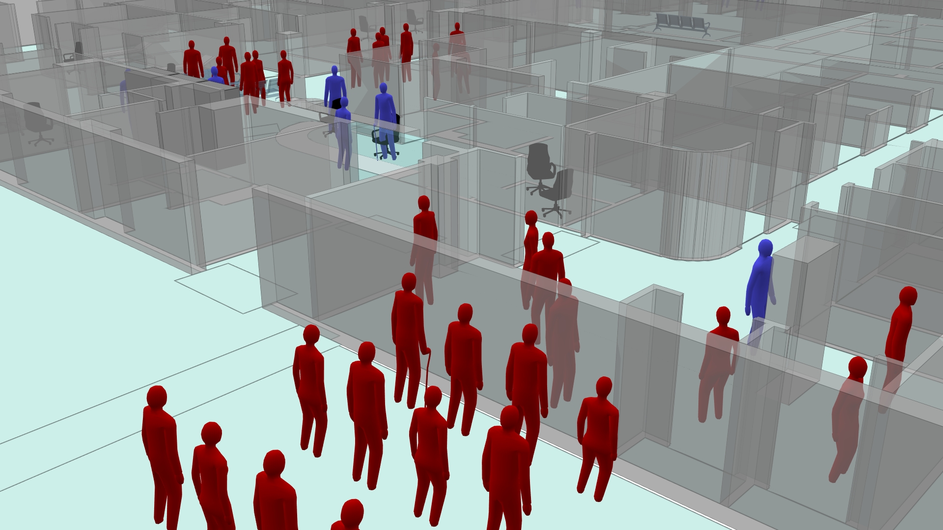
Pedestrian simulation
Oasys MassMotion wins award for Best Innovation at the CogX Awards
Posted March 18th 2022

Pedestrian simulation
Blooloop Innovation Awards 2021
Posted October 20th 2021
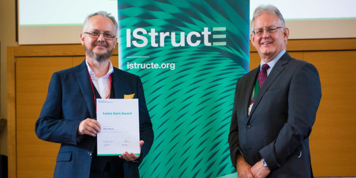
Oasys
Peter Debney wins Lewis Kent Award
Posted October 1st 2021

Oasys
Computational Engineering by Peter Debney
Posted May 22nd 2020
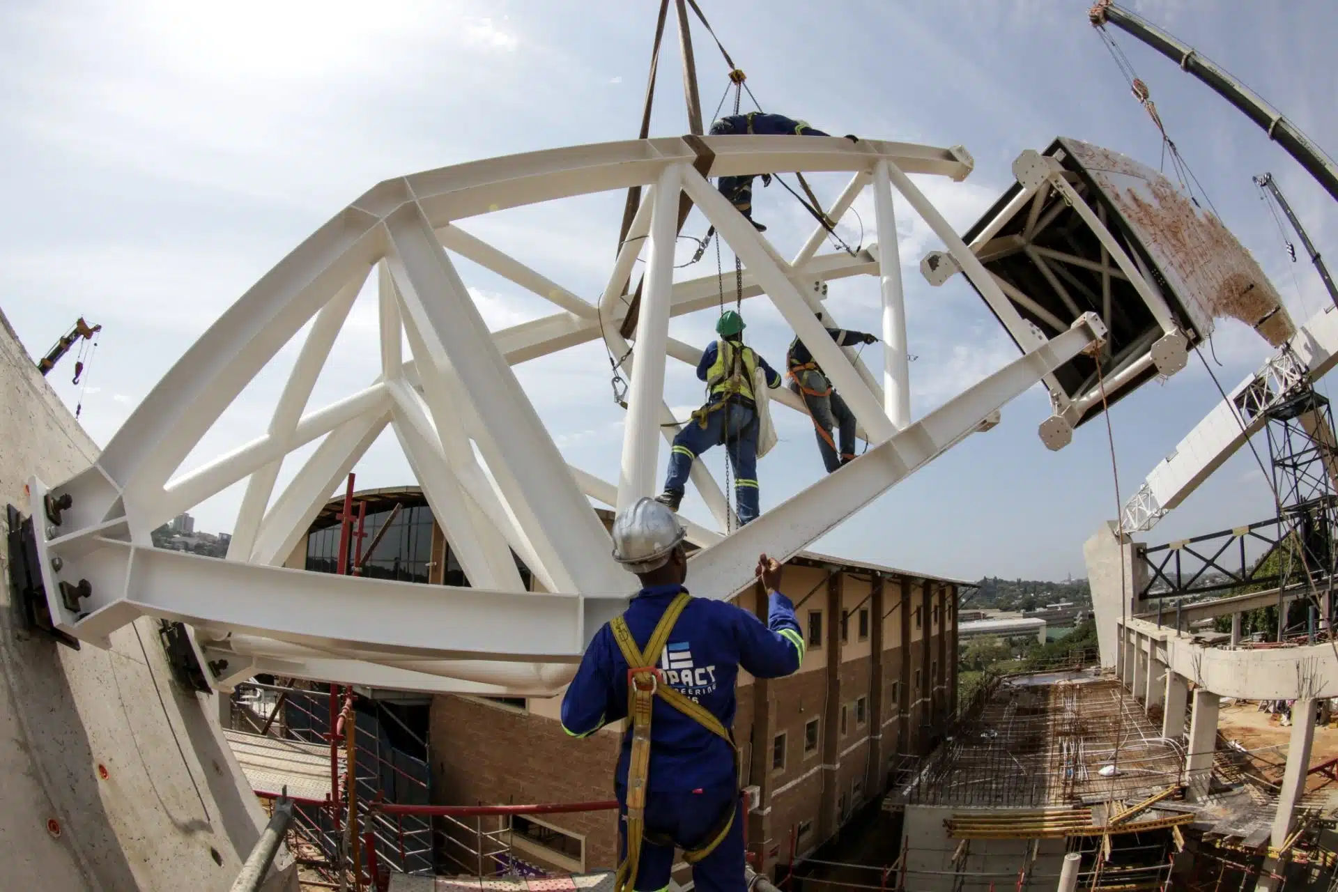
Structural engineering
Durban Christian Centre team wins National Steel Award
Posted November 12th 2019