Case studies
Explore real‑world engineering case studies showcasing how Oasys software is used to solve geotechnical, structural, and pedestrian modelling challenges.
Featured case study
Structural engineering
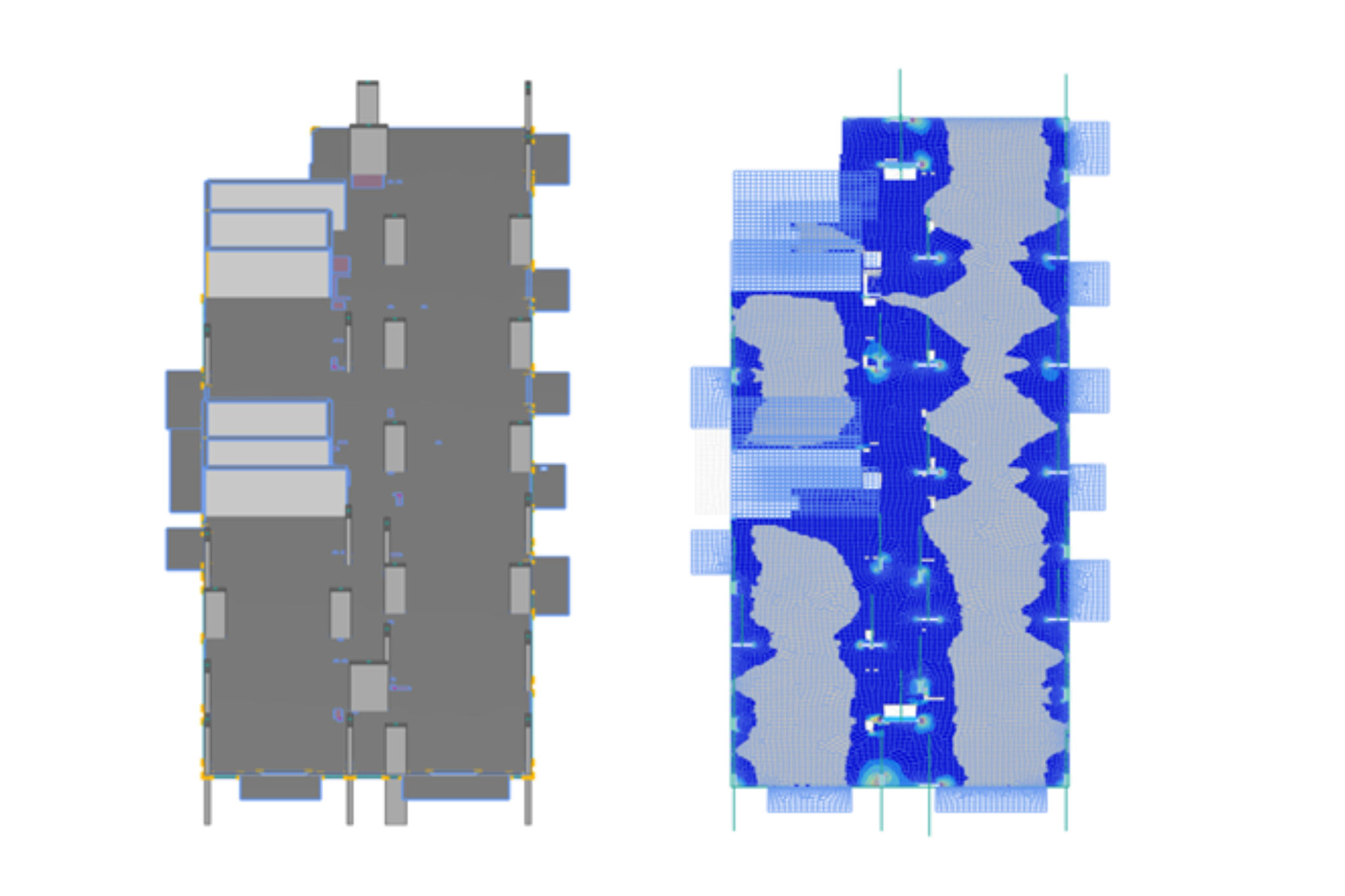
RC Flat Slab Automation: Iterative Post-Processing of Oasys GSA Results
This case study explores how Arup developed a fully digital, automated workflow for designing flat slab RC frames using Oasys GSA. By combining GSA analysis results with the GSA API and Grasshopper, the team accelerated the design of complex, multi-storey residential buildings with repeatable floorplates.
Read Case Study
Structural engineering
RC flat slab automation: Iterative post-processing of Oasys GSA results
During the work on several residential masterplans in London, Arup developed a digital workflow for the design of flat slab RC frames, fully based on Oasys GSA analysis results, implementing the…
Read More
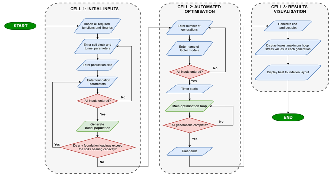
Geotechnical engineering
Investigating automated optimisation of foundation design
This research project carried out by Durham University MEng student Arthur Chai, in collaboration with Arup and Oasys, addresses the complex challenge of foundation design and impact assessment in civil engineering. This area plays a crucial role in ensuring…
Read More
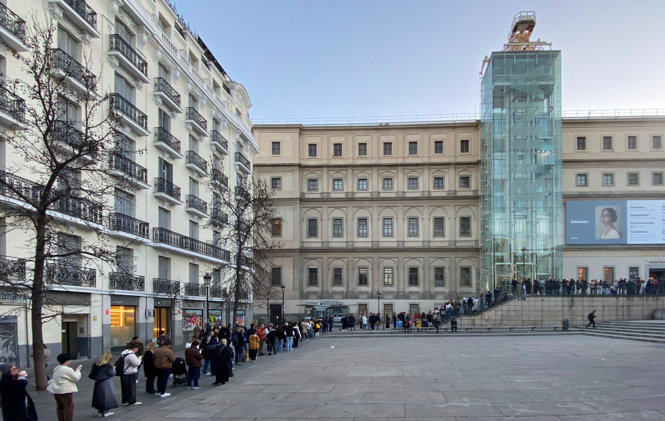
Pedestrian simulation
Improving visitor experience at the Reina Sofía Museum in Madrid
The Reina Sofía is one of the most important museums in Madrid and Spain. With over 1.5 million visitors in 2024, it ranked among…
Read More
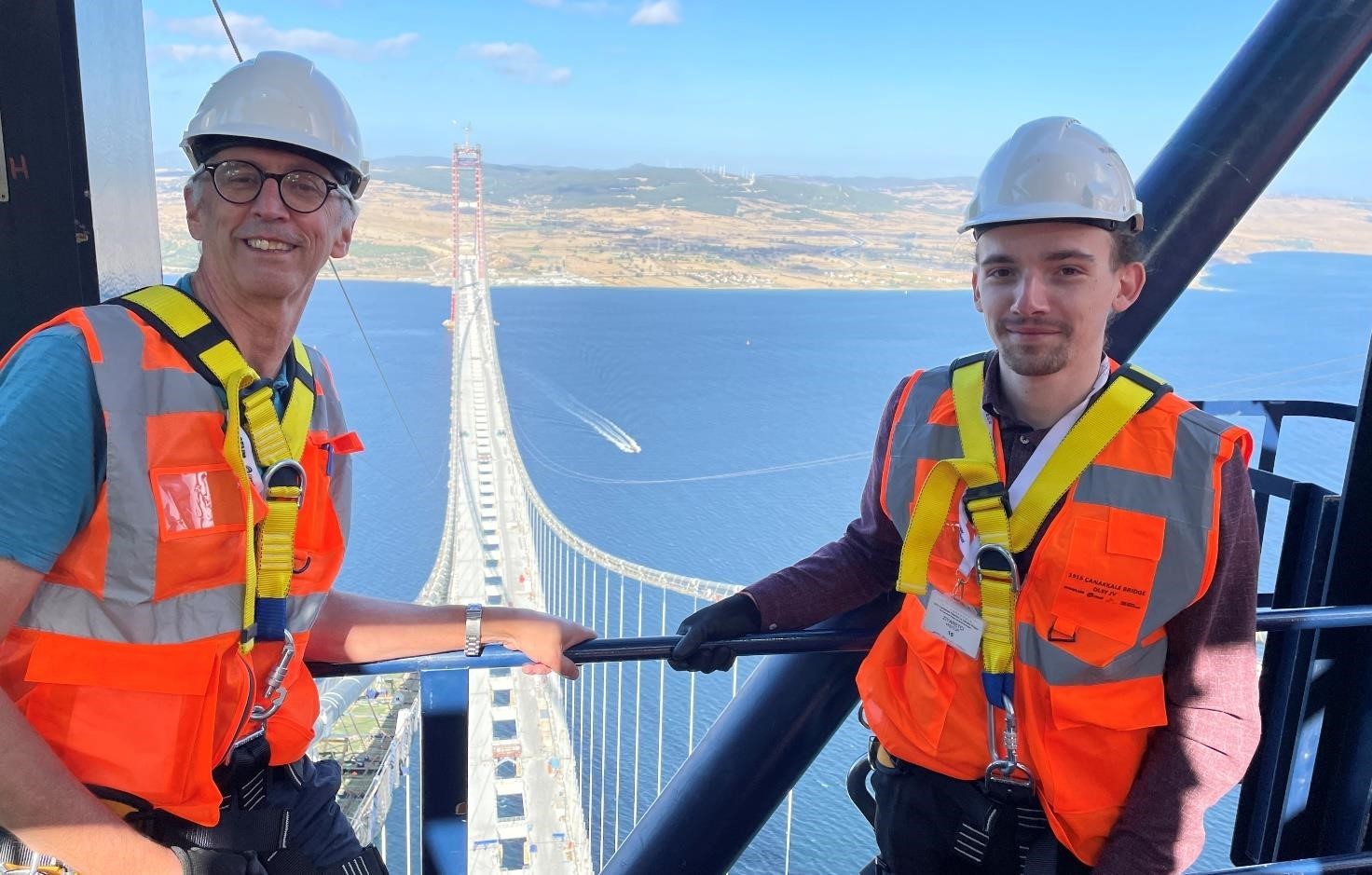
Structural engineering
How Arup used Oasys Structural software to verify the design of the 1915 Çanakkale Bridge
The 1915 Çanakkale Bridge is a long-span suspension bridge crossing over the Dardanelles straits in Turkey. In line with UN SDG 11, the bridge…
Read More
Structural engineering
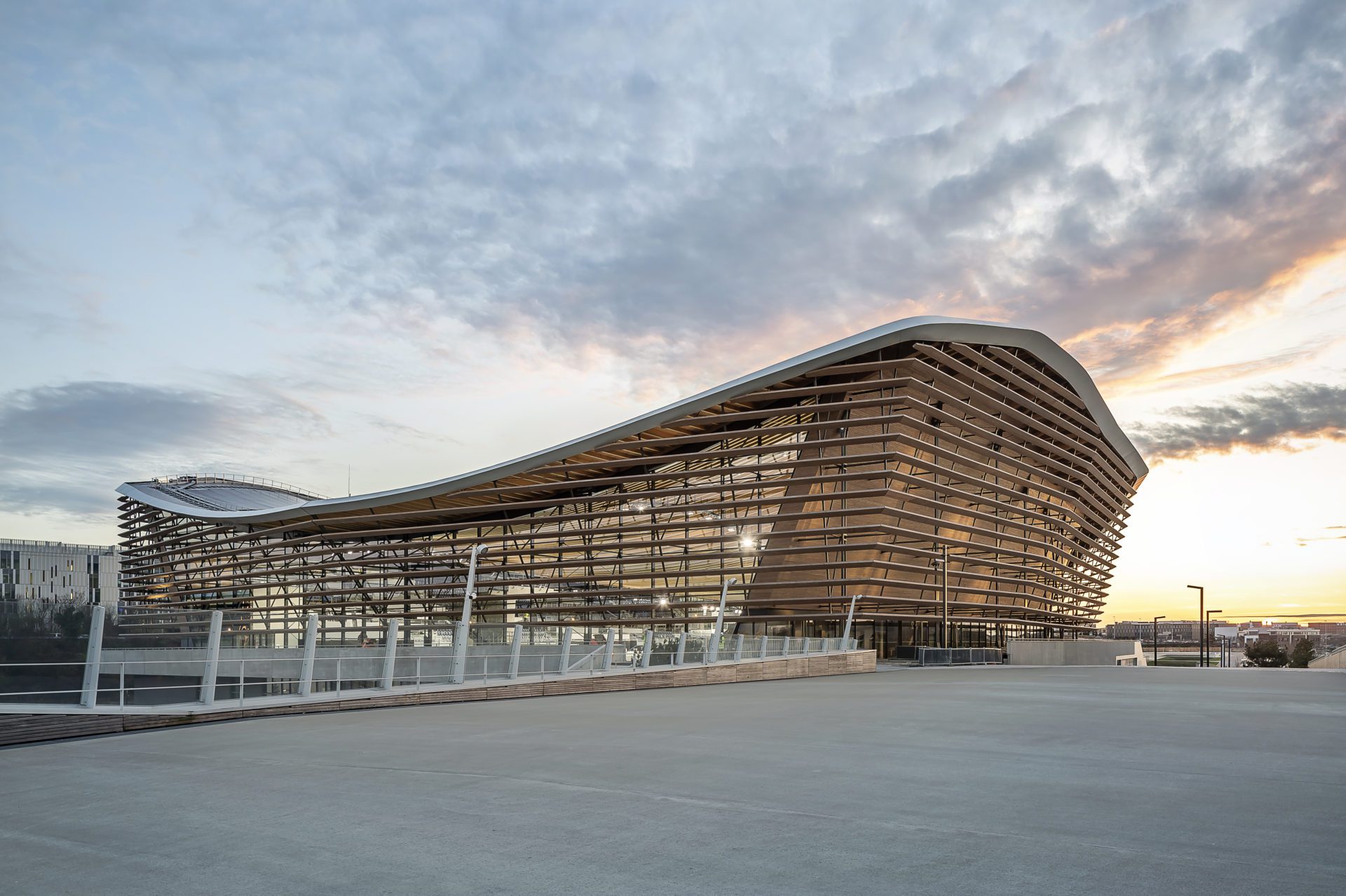
Ambitious technical innovations for sustainable design: Olympic Aquatics Centre, Paris 2024
The Aquatics Centre in Saint-Denis, built for the Paris 2024 Olympic and Paralympic Games, is a multi-award-winning marvel. Designed by schlaich bergermann partner (sbp) in collaboration with architects VenhoevenCS and Ateliers…
Read More
Structural engineering
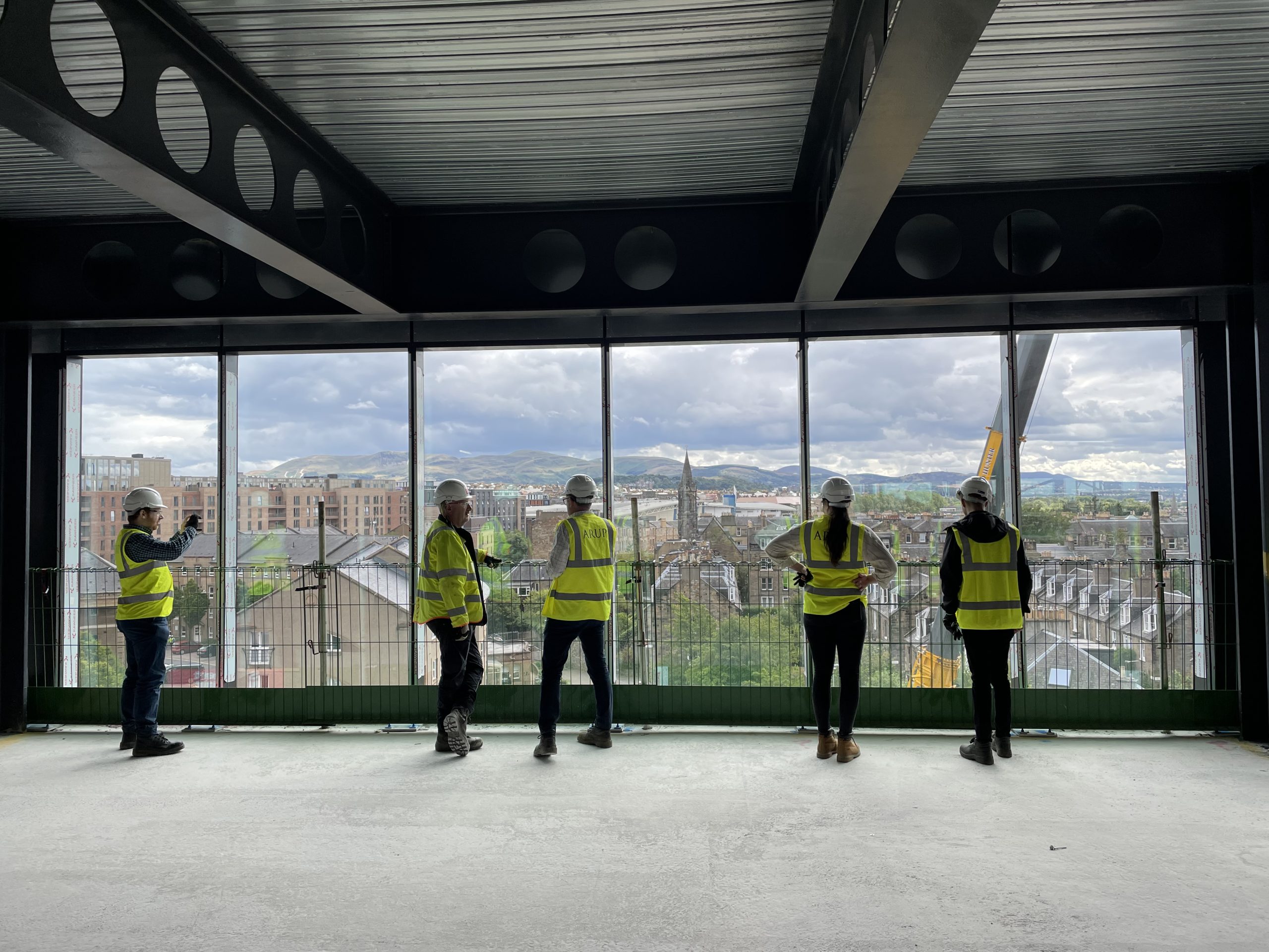
Seamless software integration drives efficiency for the Haymarket Edinburgh project
The Haymarket project in Edinburgh, commissioned by M&G Real Estate with QMile Group and designed by Foster + Partners, is a testament to innovative engineering and architectural excellence. Engineered by Arup, this mixed-use…
Read More
Structural engineering
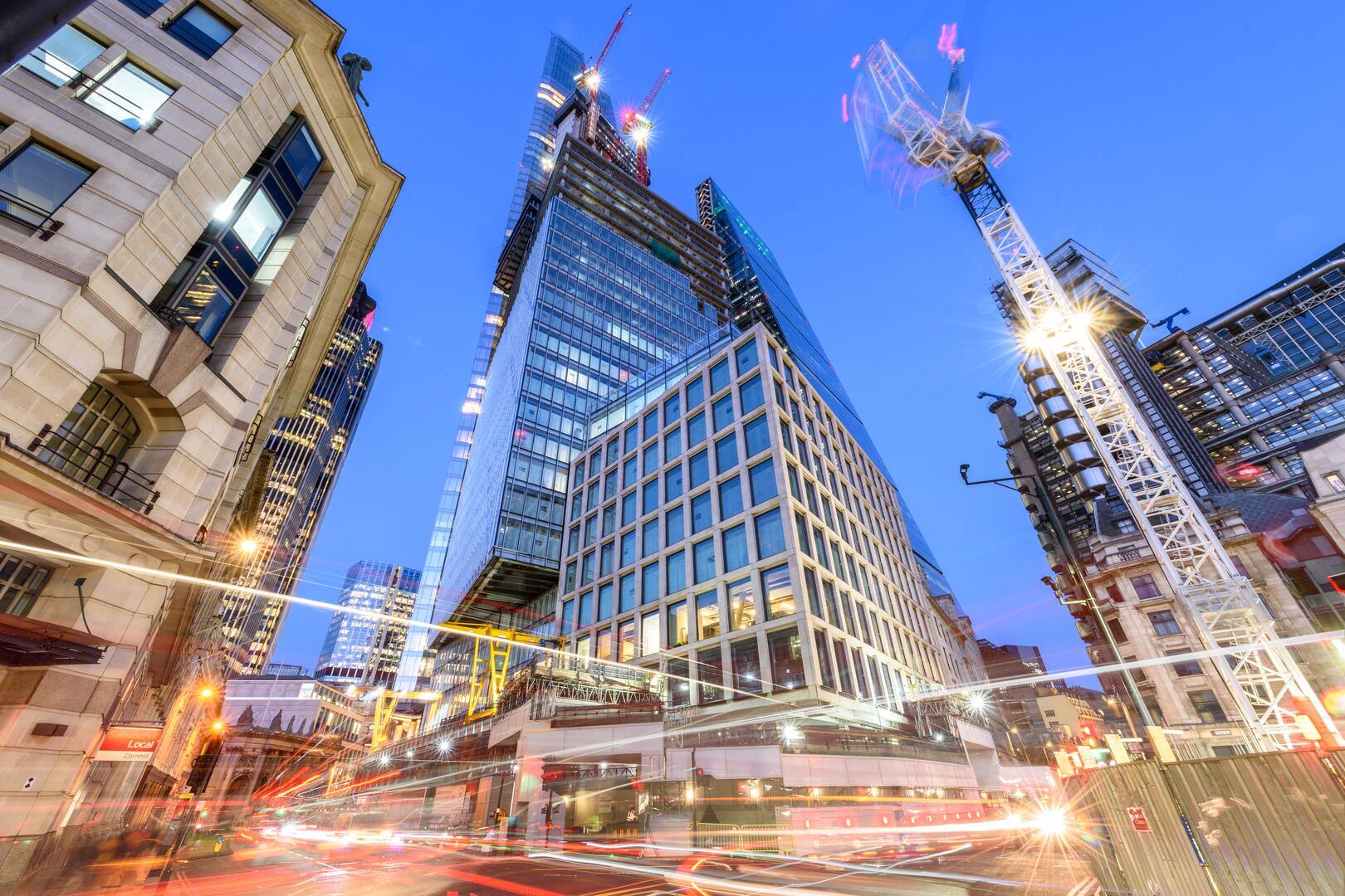
Powerful structural design and analysis of 8 Bishopsgate, London
Awarded ‘BCO London Best Commercial Workspace 2024’, ‘CTBUH Best Tall Building in Europe 2024’ and ‘CTBUH Best Tall Building by Height (200-299m) 2024’, and shortlisted at…
Read More
Structural engineering
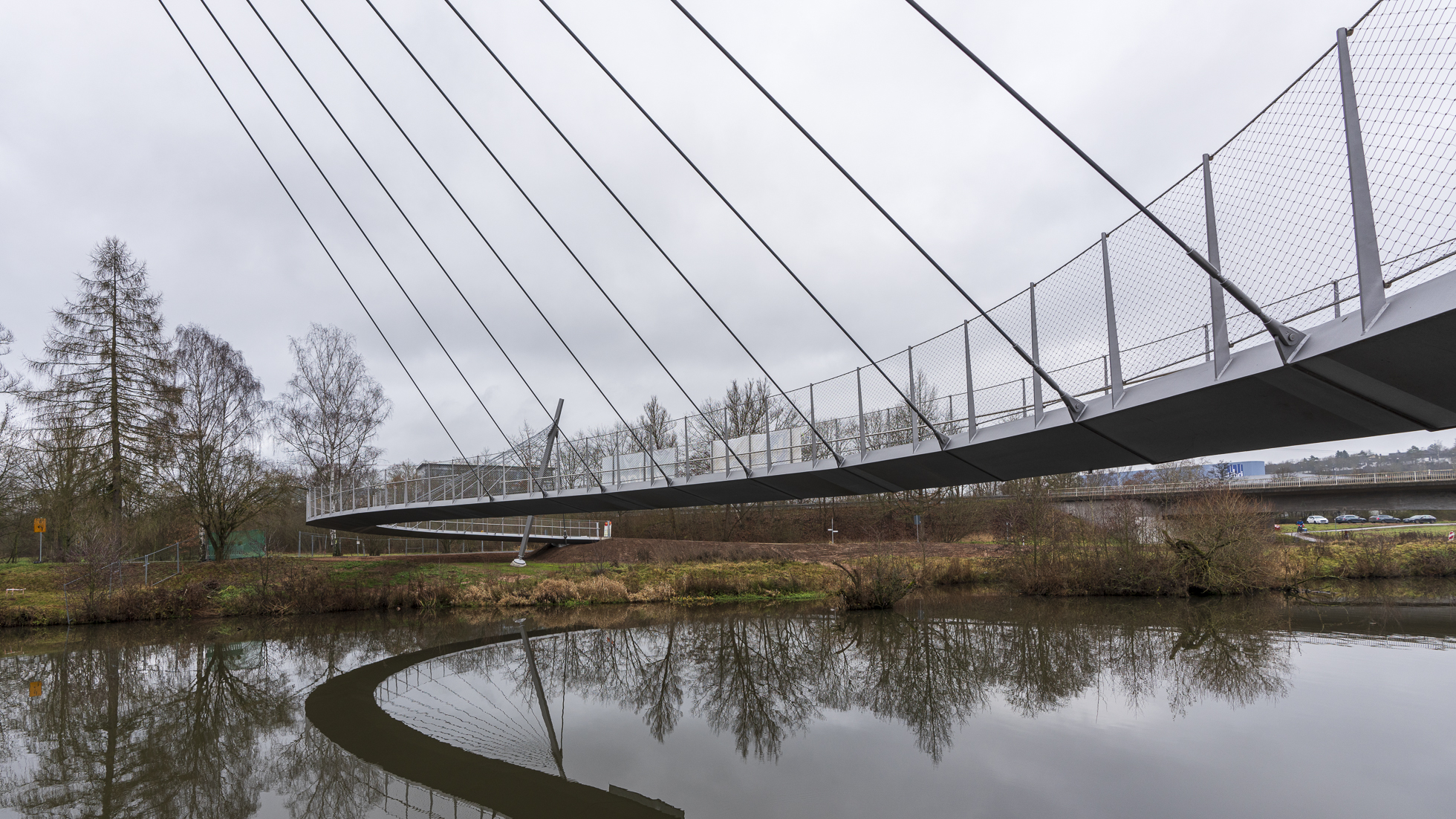
Structural design and dynamic assessment of an asymmetric cable-stayed footbridge
In the small town of Bad Hersfeld in Germany, schlaich bergermann partner (sbp) designed a pedestrian and bicycle bridge crossing the river Fulda. The footbridge was…
Read More
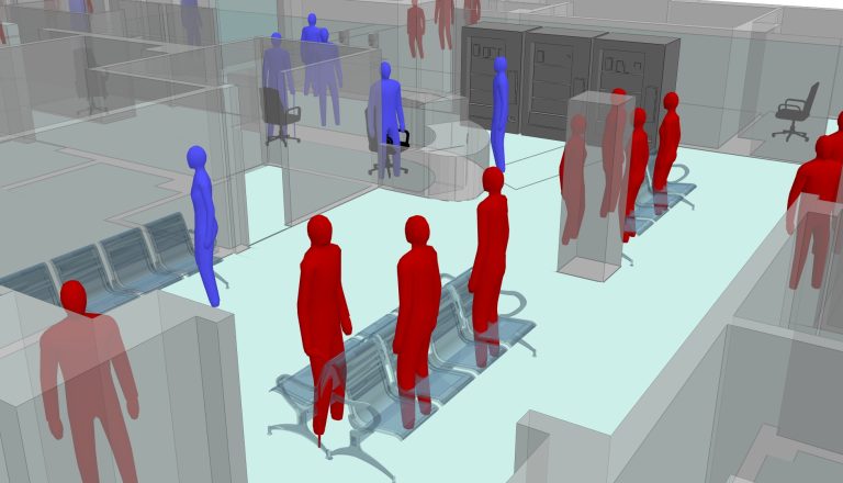
Pedestrian simulation
Whittington Emergency Department capacity modelling using Oasys MassMotion
During the COVID-19 pandemic, the NHS came under major strains in more ways than one. With winter 2020 fast approaching as a crucially busy…
Read More
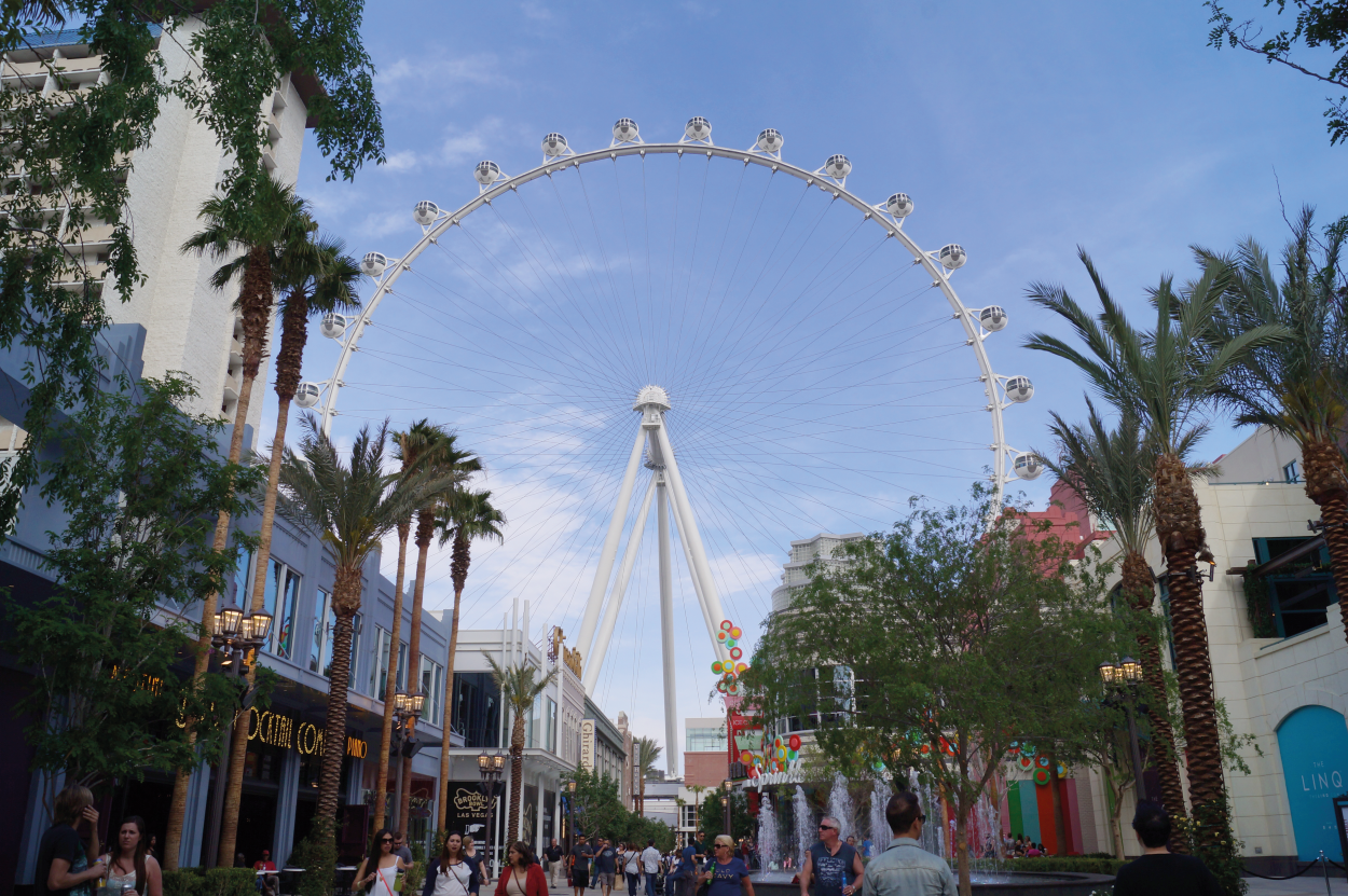
Structural engineering
Intricate analysis and design of Las Vegas High Roller observation wheel
The Las Vegas High Roller opened in 2014 as the largest observation wheel in the world (it is now the second largest, after the Ain Dubai (Dubai…
Read More
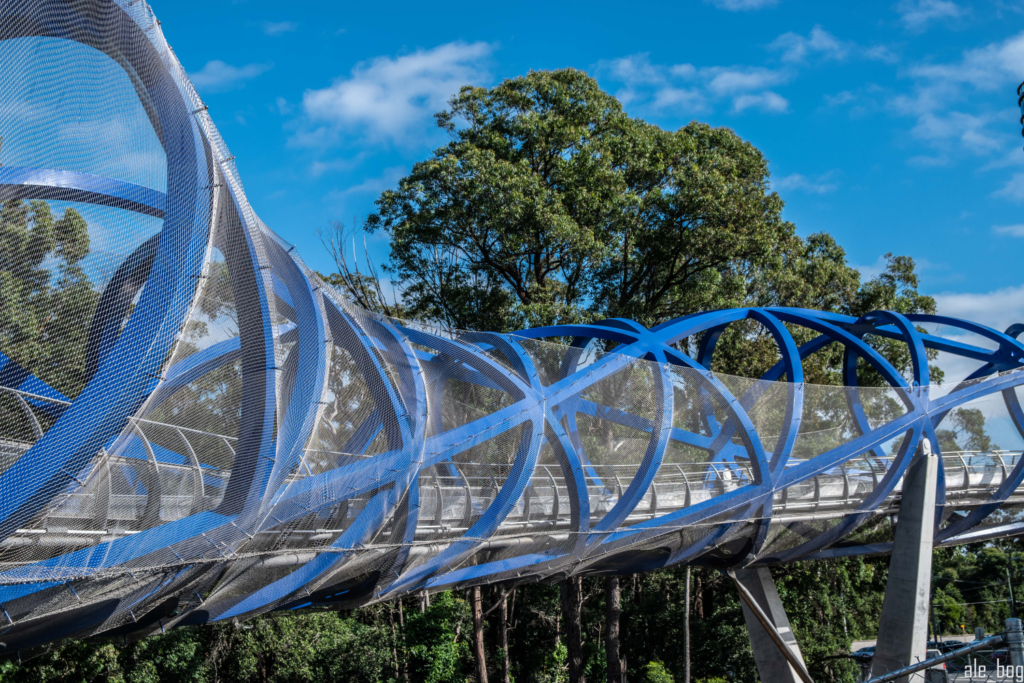
Structural engineering
Sydney’s double helix bridge at Lachlan’s Line
The digital engineering-led approach to the project from concept to completion of this unique ‘double helix’ bridge in Sydney, Australia, has delivered a successful…
Read More
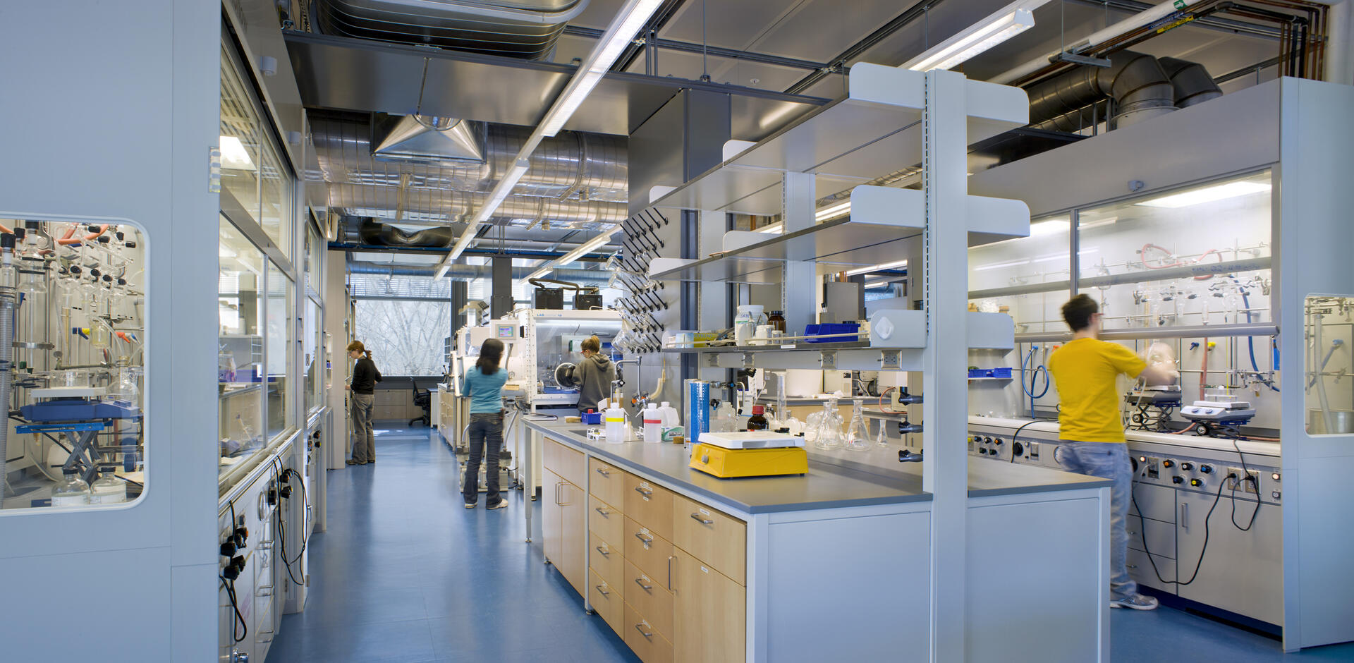
Structural engineering
Princeton University, frick laboratory
Arup’s multidisciplinary design for Princeton University’s new Frick Laboratory had to meet major challenges, balancing the rigorous vibration and cleanliness requirements with the University’s…
Read More
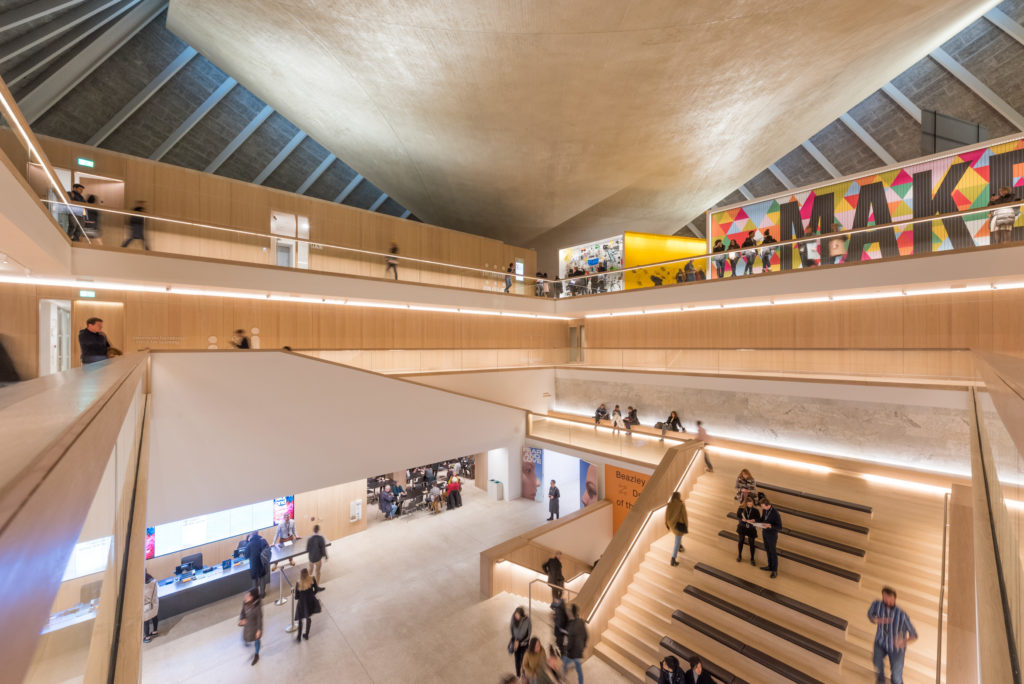
Structural engineering
Design Museum, London
Oasys GSA and Oasys AdSec helped Arup structural engineers to preserve the stunning 1960s hyperbolic paraboloid (“saddle”) copper-clad concrete roof at the new home of London’s Design…
Read More
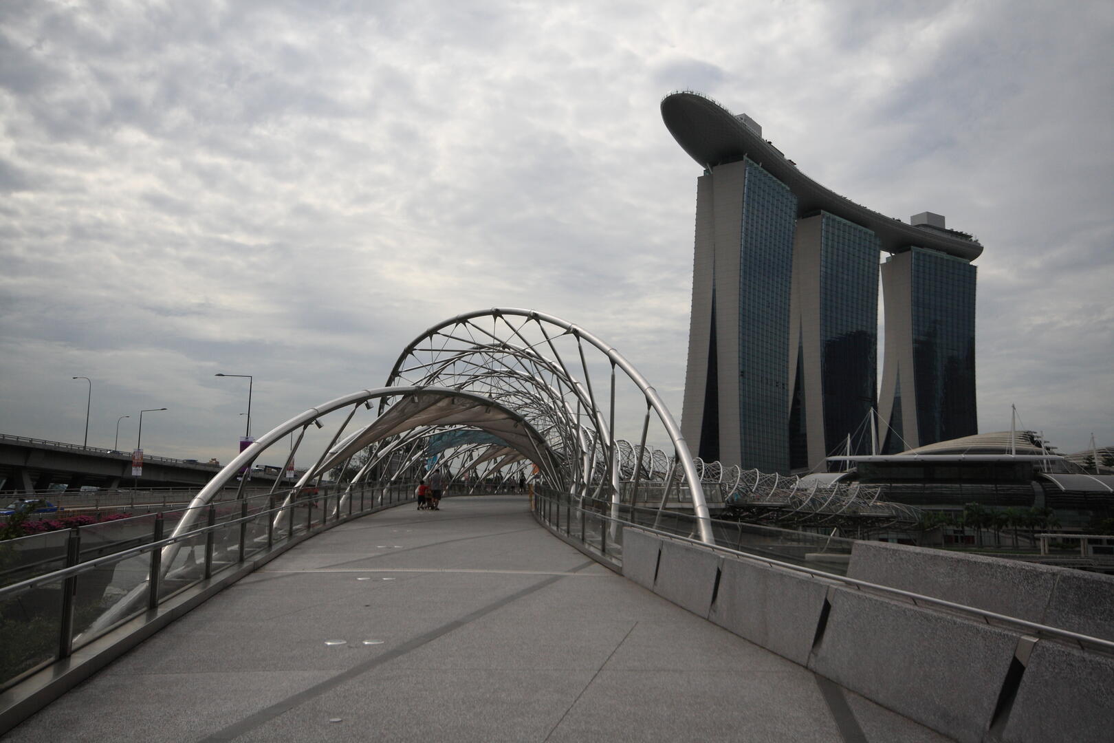
Structural engineering
Footfall analysis for Singapore’s Helix Bridge
The elegantly curved 3.5km Helix footbridge with its four cantilevered viewing pods is a focal point of Singapore’s Marina Bay development. Its design, inspired by…
Read More
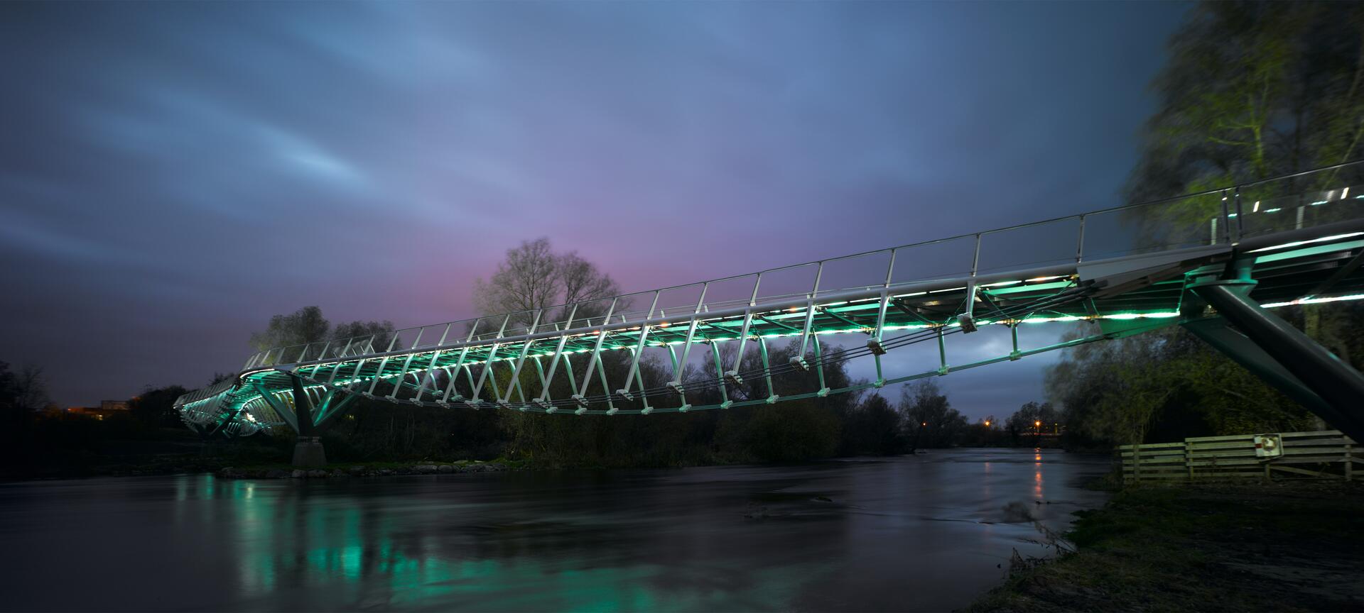
Structural engineering
Living Bridge, University of Limerick
With the aim of creating a new ‘living link’ between the University of Limerick’s established campus and its developing annex across the River Shannon,…
Read More
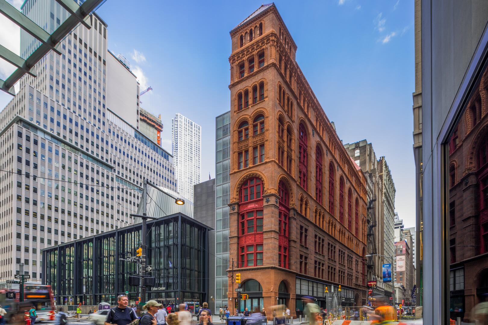
Pedestrian simulation
New York’s Fulton Center
Engineered by Arup as the prime design consultant, New York’s newest transport hub, the Fulton Center, was opened in 2014 with capacity to serve…
Read More
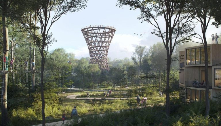
Structural engineering
Structural design and analysis of hyperboloid lattice tower
The Camp Adventure Forest Tower opened in the summer of 2018 and is part of an existing sports facility that incorporates treetop climbing paths and aerial…
Read More
Trusted by over 6,000 users on a range of projects across the globe


Calling Oasys community!
Got a case study about using Oasys software to share? Get in touch – we’d love to help you share your success stories.