GSA – Beam element axes definition
Axes are key to the geometric description of an analysis model. When the structure is nice and rectangular, with gridlines parallel to the compass, the default axes are all that’s needed. But when beams start veering off or curving round, getting clever with the axes can save you a lot of problems.

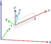
Once you have defined where the beam ends are in space, you then need to ensure that they are the right way around. After all, I beams are much stronger in one direction so you need to get it right. The local axes of a beam are also defined in terms of x, y and z (but lower case). The local x axis comes first, as the vector from the start to the end of the beam. The local z is then as close to the global Z as possible while keeping it perpendicular to the local x – this means that a beam web will be vertical, unless you add a rotation onto the member. Finally, the local y is the perpendicular to the local xz plane.

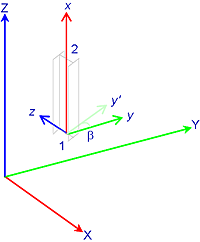
For a column, that is vertical beams, the rules have to change as the local z axis is now horizontal. Now, the beam is orientated by making the local y match the global Y.
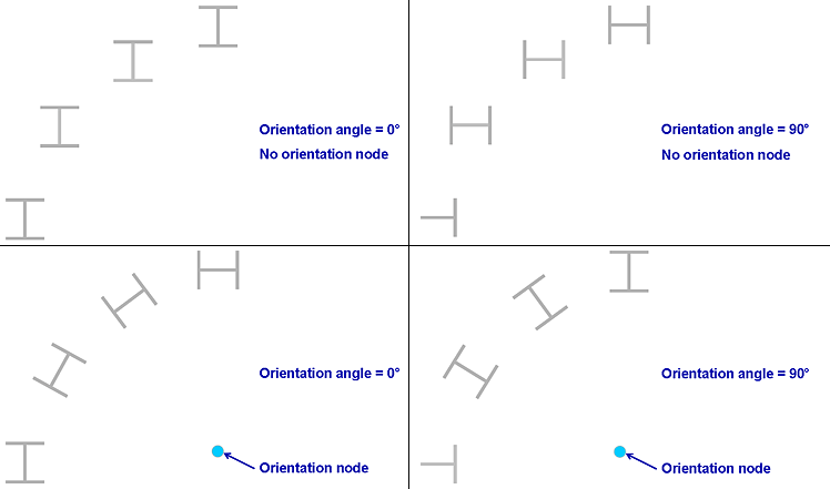
While beams may usually be aligned so that the major axis is vertical, columns typically need aligning. With GSA there are two ways of doing this: one is to set a rotation and one is to align the rotation to a separate node. Orientating to a node is ideal if your grid is at an angle and you are not quite sure what it is, or if you have a circular building or façade on an arc. It also comes in useful for aligning beams on.
You can of course use a combination of them both to get the orientation that you want.

