GSA – Axes in GSA
Axes are essential to the geometric description of a GSA model. When the structure is orthogonal, the default axes are all that are needed. But when beams and grids start veering off or curving round, getting clever with the axes can save you a lot of problems.
Global axes
Standard axes are provided by GSA. Of these, the most fundamental is the global axis set. All other axes, whether standard, implicit, or explicitly defined axes are defined with respect to the global axis set. GSA adopts the convention that axes labelled with uppercase X,Y,Z are in global axes; otherwise lowercase axis labels are used.
Use of axes
Nodal coordinates are defined with respect to an axis set. Usually this is the global axis set, though this can be changed by setting the ‘current grid’. (See below.)
Nodal constraints act in constraint axis directions. This defaults to global, but can be set to any standard or user defined axis set.
Element axes are often defined in terms of the element topology, though several element types can have their element axes defined by reference to a particular axis set.
Results are usually reported in output axes directions. These default either to global directions or to element axis directions, depending on the result type. Many results can be transformed from these default directions to specified output axis directions by overriding the default output axes.
Axis set definition
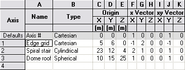
Axis sets are specified as being one of these three types:
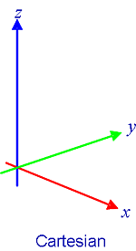
- Cartesian, in which coordinates are defined in terms of lengths along each orthogonal axis. (Global axes are Cartesian.) Cartesian axes are good for structures in which the members are typically at right angles to each other.
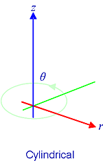
- Cylindrical, in which coordinates are defined in terms of the plan distance from the origin (r), the angle about the z axis (θ), and the length along the z axis. Cylindrical axes are good for when working with spiral staircases and round buildings.
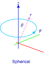
- Spherical, in which coordinates are defined in terms of the radius (r), an angle about z (φ), and an angle of inclination from z (θ).
For cylindrical axes, the x vector is the direction of zero rotation (θ=0) and the xy vector defines the z=0 plane of the cylinder.
Axis sets have an origin, specified in global directions.
 Cartesian axis sets are oriented by means of an x vector that defines the direction of the x axis from the origin, and an xy vector that, together with the x vector, defines the xy plane. Both of these vectors are defined in global directions. (N.b the xy vector does not need to point exactly in the intended y axis direction.) The z axis is orthogonal to the xy plane.
For sperical axes, the x vector is the direction of zero rotation (φ=0) and the xy vectordefines the plane of 90° rotation (θ=90).
Standard axes
In addition to global axes, GSA provides several standard axis sets, including cartesian axes in the YZ and ZX planes, and cylindrical and spherical axis in the XY plane.
User defined axes
You can define user axes as Cartesian, cylindrical or spherical. Unlike the global axes and other standard axes, these might have their origin somewhere other than 0,0,0 and might be rotated from the global directions. For example, if you have an area of structural grid that is skew to the rest of the building, then you will need a user defined axis, with the origin set at the ‘hinge’, and oriented to align with that part of the structure.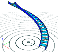
Grid Planes
Grid planes are related to axes, in that you refer to an axis set and z elevation to define a grid plane. A grid plane may be thought of as a virtual surface in the GSA model. As with axes, GSA provides standard grid planes, and you may define others.
The ‘Current Grid’
The current grid is the grid plane in which nodal coordinates are currently reported and defined. In Graphic Views the grid is displayed on the Current Grid. The name of the current grid is displayed in the status bar, and can be specified via ‘Data | Define Current Grid”.
