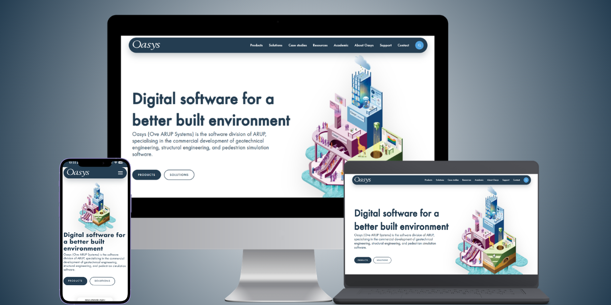
Digital software for a better built environment
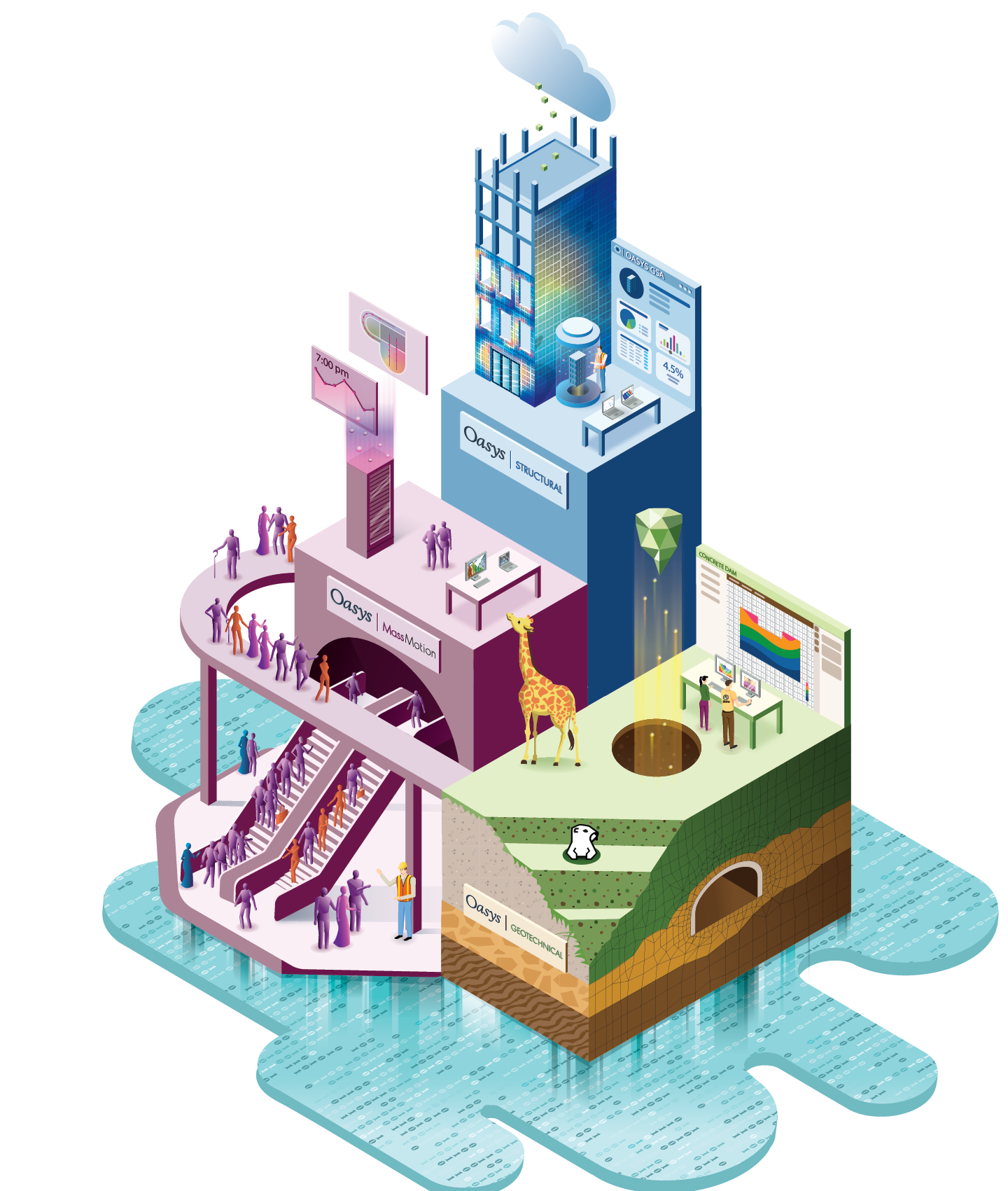
Oasys (Ove Arup Systems) is the software division of Arup, specialising in the commercial development of geotechnical engineering, structural engineering, and pedestrian simulation software.
Search across articles, pages, products, case studies, and webinars with instant suggestions as you type.
Products
Browse our range of geotechnical, structural and pedestrian simulation products.
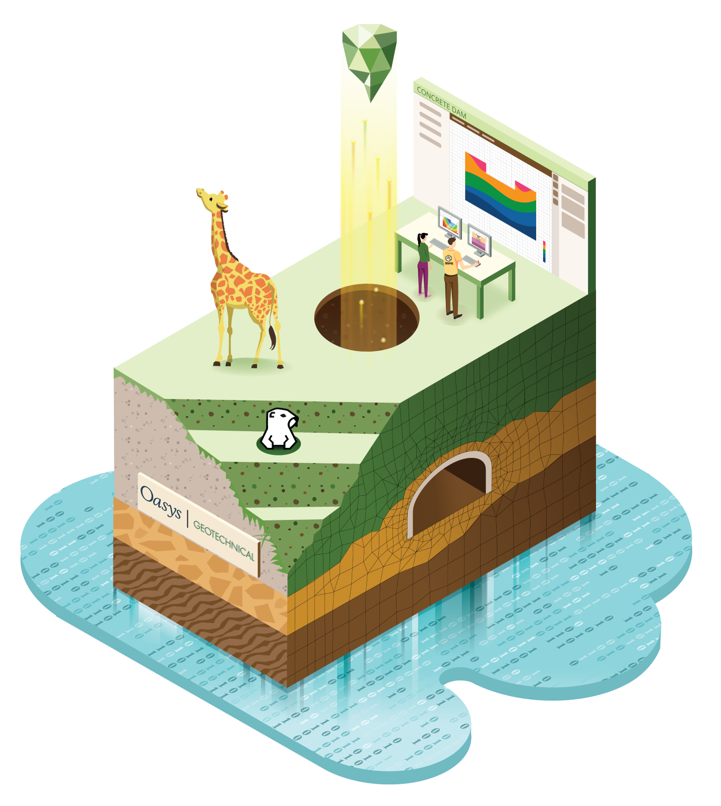
Oasys Geotechnical
Oasys geotechnical engineering software provides engineers with a range of calculations for assessing and quantifying ground movements and soil behaviour.
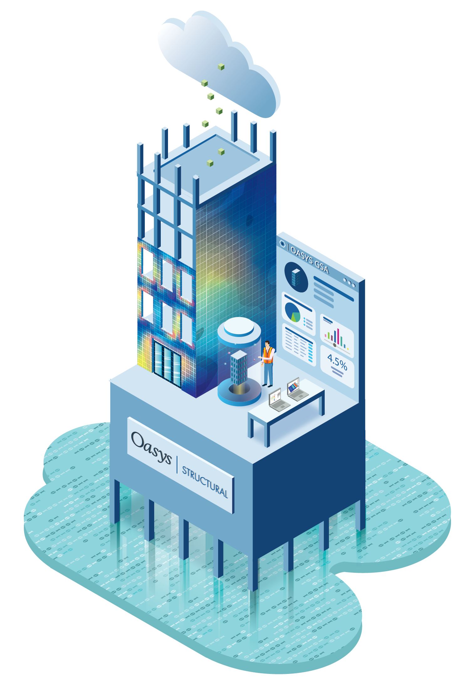
Oasys Structural
Oasys structural engineering software offers comprehensive and robust design and analysis for basic low-rise structures to the most complex specialist structures.

Oasys MassMotion
Oasys MassMotion is our pedestrian simulation software trusted by engineers, designers, planners, architects, and operators for designing human-centric spaces.
Solutions by project specification
Oasys software provides detailed design, analysis and modelling across multiple applications. Browse our solutions to understand how our software can help you deliver successful project outcomes.
Flexible retaining wall analysis
Pile analysis and foundation design
Ground movement and stability analysis
Geotechnical graphing
Building and bridge design
Computational design
Vibration and seismic analysis
Pedestrian simulation
Latest news
Keep up to date with the latest news, events and announcements.
Oasys
A refreshed Oasys website built with you in mind
Posted April 28th 2026
Oasys
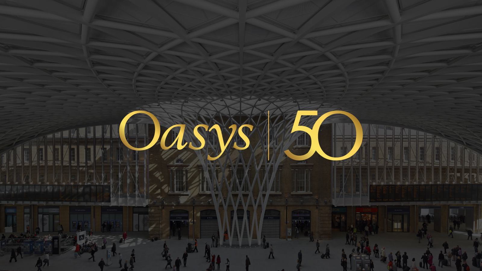
Celebrating half a century of software development
Posted April 16th 2026
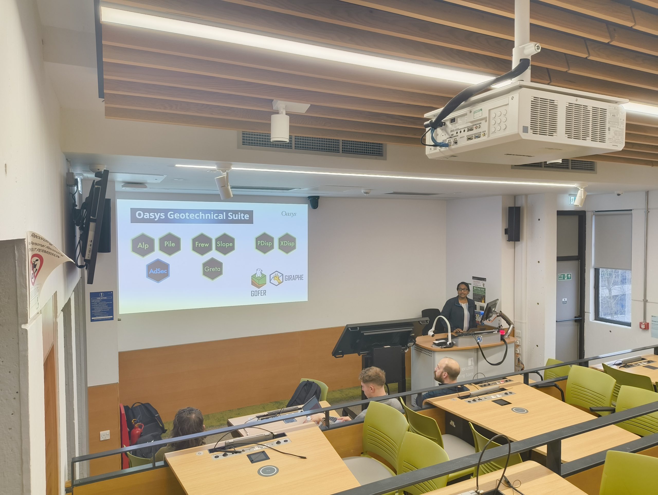
Geotechnical engineering
Bringing real‑world ground engineering to the University of Leeds
Posted March 27th 2026
Trusted by over 6,000 users in more than 40 countries


Latest case studies
Engineers across the world have relied on our software for 50 years to deliver a variety of projects to a range of clients.
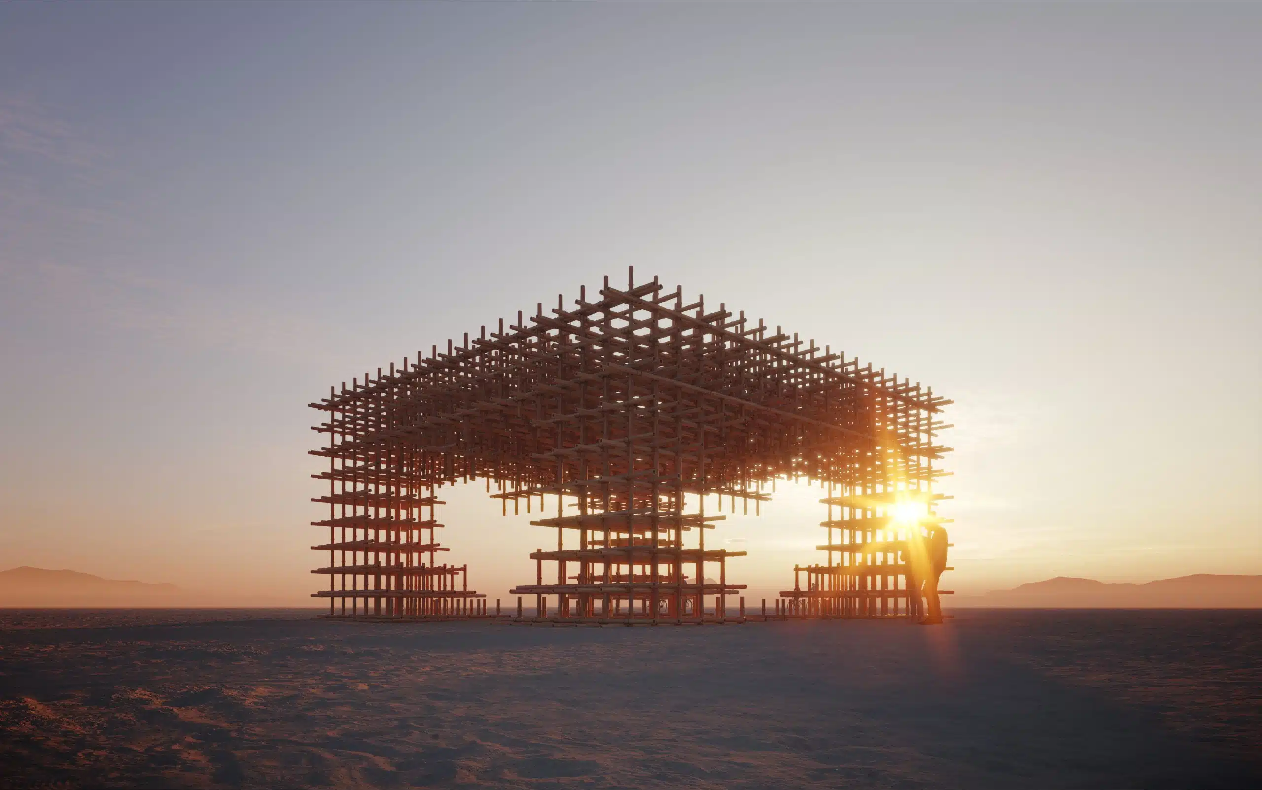
Structural engineering
Structural analysis and design of a bamboo art installation using Oasys GSA
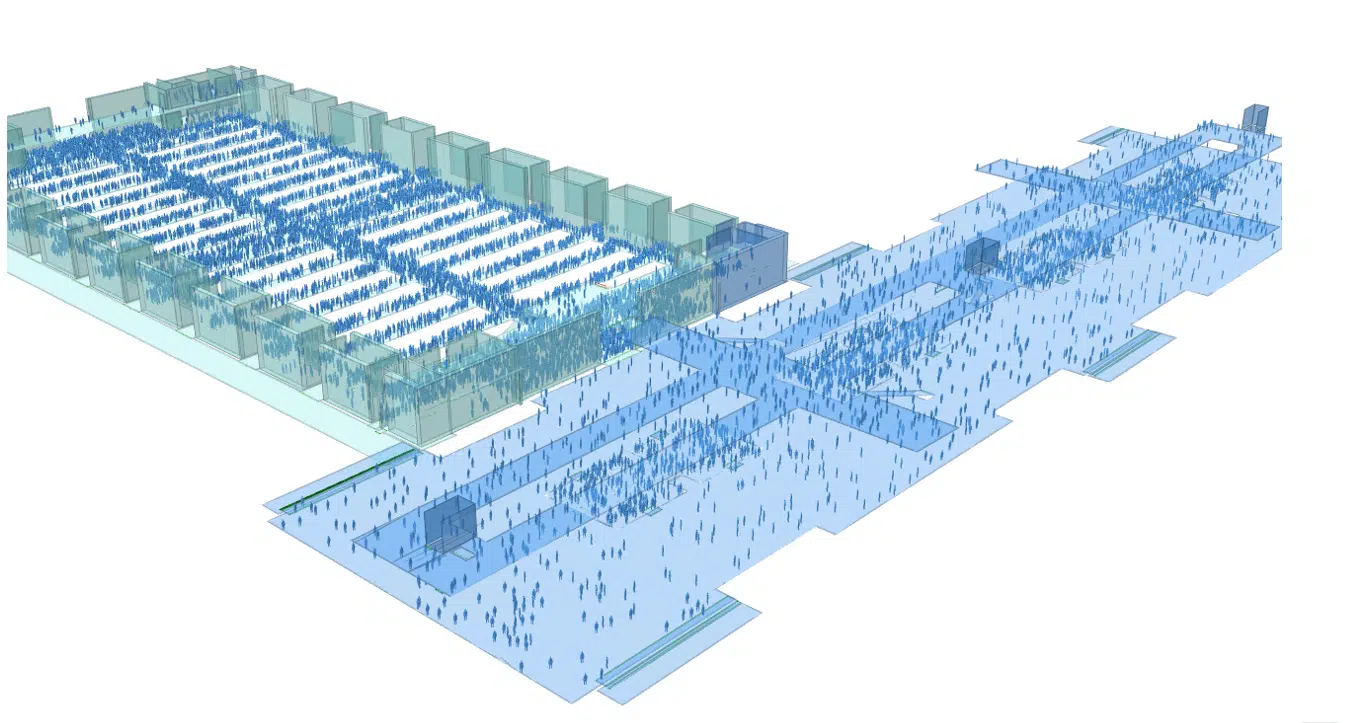
Pedestrian simulation
Delivering fire safety solutions for mega-span exhibition buildings
Structural engineering