Cracking the Code: Exploring the Options for Casting Models in Crash Analysis

Image source: Example crash model with large casting in rear floor structure
Over the last 30 years, there have been significant changes in the approach to automotive body architecture and material selection. In response, the methods we use to analyse these structures have also changed. In this article, we discuss some of the challenges around the increased use of aluminium castings in automotive bodies and how we can address them using Ansys LS-DYNA.
As we entered the present century, we witnessed an increase in the use of aluminium in body design, in both the premium sector and the smaller segments, e.g. the Audi A2. One primary attraction of aluminium over the traditional choice of steel is its density, which is two thirds lower, boosting fuel efficiency and performance. Aluminium is abundant in Earth’s crust, although it requires more energy to extract than steel, which can increase cost. There are many options for shaping aluminium, for example extrusions, where the material is squeezed through a die to form long prismatic sections which can be joined into frames or integrated into unibodies. Extrusion dies are generally cheaper than press tools, therefore a car body that utilises aluminium extrusions has the potential to be both lighter and more cost efficient to tool than traditional steel, enabling smaller runs of vehicles.

Image source: Audi A2, © Audi AG
Yet there are downsides to aluminium that cannot be ignored:
- Firstly, like density, the Young’s Modulus is about one third of steel’s. This can affect the stiffness of the car body unless accounted for by design.
- Aluminium extrusions and pressings typically cannot be made as thinly as steel – meaning that in some areas extra material must be carried whether it is needed or not.
- The range of strength is not as wide for aluminium as it is with steel. Some of the more expensive alloys have yield strengths that compare to mid-strength steels, but it is currently a challenge to compete with the almost indestructible properties of boron hot stamped steels, often used to reinforce passenger compartments.
- During the extrusion process the section remains constant along its length – again material may be an unwanted passenger, unless removed with an additional process.
- Joining the extrusions together can be a challenge. One solution is to use aluminium castings as nodal connectors, providing sockets for converging extrusions like the poles in a tent.
What are the latest advances in aluminium body design?
Castings provide huge freedom for material placement and variation of thickness in a single part. In recent years we have seen the adoption of very large castings to replace whole regions of body structure in one go, the advantage being that a single part can replace dozens of smaller ones and the associated joining. This could lead to faster assembly and new design freedom in terms of integration and structural continuity. There are challenges to consider – casting alloys have a limited range of strength and parts are often thicker than equivalent pressed or extruded parts. Investment in tooling is high and the ductility and repairability of the parts are often challenged.
What does the proliferation of castings mean for the CAE engineer and tasked crash analysis using the explicit solver in Ansys LS-DYNA?
Castings can be geometrically complex, with varying wall thicknesses and solid features that do not lend themselves to meshing in 2D shell elements, the mesher’s favourite and time-tested stalwart of crash analysis. Most of the advances in meshing technology in the past decades have been to automate the meshing of pressed parts using shell elements; meshing solid parts in 3D elements has not been automated to the same extent.
One solution is to use tetrahedral elements, which can be generated quickly but are not always accurate unless meshed very finely. Smaller elements lead to a higher element count and a smaller solution timestep – which both impact simulation run times. The issue is compounded when a growing percentage of the body structure is taken up with castings, raising the question; will engineers need to manage much longer run times and unwieldy model sizes?
Unlocking the Full Power of Ansys LS-DYNA for Advanced Problem Solving
At Arup, we are exploring a number of the advanced options available in the Ansys LS-DYNA solver to help us work with large castings:
- Higher order tetrahedral elements
- Selective mass scaling
- Iso-Geometric Analysis (IGA)
We believe IGA has the potential to revolutionise the traditional meshed approach but has yet to emerge fully. We are supporting the growth of this technology with comprehensive tools in the Oasys software.
Ansys LS-DYNA offers a selection of tetrahedral elements*, the most-used being the 4-noded element formulations 10 and 13. Of these, type 13 has been shown to be more suitable for structural analysis because of reduced volumetric locking. The challenge with linear tetrahedrons is that a fine mesh density is required to achieve convergence in benchmark tests. Ansys LS-DYNA also offers 10-noded tetrahedral elements as type 16 and 17. As the figure below shows, these higher order elements converge much more quickly than the 4-noded elements, when extracting the moment from a simple beam model.
* You can read about the solid elements available in Ansys LS-DYNA in the following article: Review of solid elements
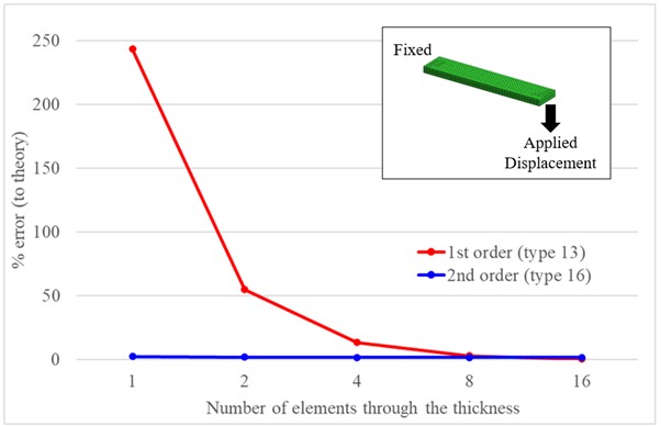
Image source: Convergence test for tetrahedral elements
Could Less Be More?
Clearly, the 10-noded elements can produce accurate results with a lower mesh density, compared to the 4-noded elements. They offer a glimmer of hope that very densely meshed models can be avoided with careful use of more capable elements. However, they come with a cost: the elements themselves are more computationally expensive, and they also require a smaller timestep, which can increase simulation run times. How can we tackle this?
Usually, elements with smaller timesteps dictate one of two outcomes – a smaller global timestep, or more added mass to satisfy the Courant condition. The downside of adding mass is that crash models become unrealistically heavy. Fortunately, a solution can be found in Selective Mass Scaling (SMS), a technology introduced to LS-DYNA in 2006. This method adds mass to elements in such a way that low-frequency modes (e.g. rigid body motion) are unaffected and only higher frequency modes see the mass. This apparent magic comes at a cost; extra time is required at each timestep to find a solution iteratively.
Is it possible to find a sweet spot where we can use SMS to increase the size of the timestep without the usual mass penalty, to run the model faster and offset its cost?
To put this theory to the test, we used an example full vehicle crash model which includes a fictitious large casting meshed in tetrahedral elements, subjected to side pole impact.
Putting the Theory to the Test
Image source: Example crash model with large casting in rear floor structure
To start with, we used 4-noded (type 13) tetrahedral elements. Our baseline model used conventional mass scaling so that a small amount of mass was added to allow a 0.5μs timestep. Changing to SMS, we were able to increase that timestep by 60% to 0.8μs. Offsetting this, each computation cycle took 50% longer than the baseline. The net effect of SMS was a runtime that was 10% faster. If we pushed the timestep any higher, key indicators such as model energy and internal forces started to diverge from the baseline solution.
With 4-noded tetrahedral elements, a very fine mesh is needed for accurate results and higher order elements can be used to address this. To explore this without a lot of remeshing, we simply substituted 10-noded (type 16) tetrahedral elements into the crash model at the same mesh density (introducing mid-side nodes between the same corner nodes).
At this mesh density with 10-noded elements, the global timestep with conventional mass-scaling would have to decrease to around 0.2μs to maintain the same amount of added mass as the baseline. Activating SMS allowed us to again achieve a timestep of 0.8μs without affecting the key indicators. The additional cost per computation cycle offsets some of this benefit, giving us a net speed increase of around 30%.
Clearly mesh size is a critical factor and the model mesh should be chosen with either 4-noded or 10-noded elements in mind. In our example, we used the same number of elements in both cases, which could imply that one of the meshes was sub-optimal.
In both cases we were able to increase the timestep significantly. Although we checked our key indicators were unaffected, this may not always be the case and model stability should be checked when using a larger timestep. Another point to be aware of is that SMS is not compatible with some Ansys LS-DYNA constraint types, although we could work around this.
Conclusion
- Ansys LS-DYNA offers a choice of tetrahedral elements, the higher order options giving accurate results with coarser meshes than would be required with 4-noded elements.
- Selective Mass Scaling (SMS) offers a real solution to the long-standing challenge of small elements driving small timesteps.
With either 4-noded or 10-noded elements, faster solutions were possible using SMS. Even if users do not wish to explore the 10-noded elements in Ansys LS-DYNA, SMS makes it possible to drastically refine the mesh in areas of interest without suffering the penalty of added mass. This applies to any element type, not just tetrahedral meshes.
Coupling this technology with other strategies to reduce run-times, such as optimised MPP decomposition, more efficient contact surface definitions or automatic run termination, could help users deal with the challenge of modelling complex castings for crash analysis.
There are many other challenges to discuss when modelling castings, including modelling of failure and the variation of material properties due to the manufacturing process. We will discuss these in a future article.
Simon Hart and Katie Lampl
Simon Hart leads the Product Engineering Practice in Arup’s Technical Specialist Services Portfolio (UKIMEA). He has 30 years of experience in the use of Computer Aided Engineering in vehicle design and leads teams of engineers working on new electric vehicle projects.
Katie Lampl is a Senior Engineer at Arup with extensive experience using Ansys LS-DYNA and the Oasys Suite for automotive design, as well as for structural and seismic analysis. You may also recognise her from our training courses, LS-DYNA technical support, or her work in barrier model development.
Simon and Katie both work closely with the Oasys LS-DYNA Environment software business and provides a link between the development of digital products and their application on engineering projects.