Software Used on this Project
Project Overview
Złote Tarasy (Golden Terraces) takes its name from Złota (Golden) Street, one of the ‘metal streets’ established in the 18th and 19th centuries in central Warsaw. Jerde Partnership of Los Angeles was appointed concept architect and Arup were brought in for the concept engineering design of the whole development.
Project overview
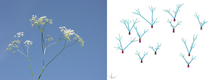
The design was inspired by the historic parks of Warsaw that were saved from wartime destruction. The main focus of the design was four retail levels grouped around a central atrium, with an undulating glass roof reminiscent of tree canopies. Canyons carve through the atrium area, allowing light to penetrate to the lowest levels, while on the south side the retail and dining areas are a series of curved terraces. Above these, the roof flows down to a sunken plaza, with pedestrian links to the station on two levels.
These terraced retail and entertainment levels are surrounded by two curved 11-storey office buildings (“Lumen”), a 22-storey office tower (“Skylight”), and a multiscreen cinema. Below ground are four basement levels, with 1,600 parking spaces. The scale of the project was immense with a total area of 200,000m² includes 54,000m² of retail, restaurants and department stores, 24,000m² of offices, an eight-screen cinema including a premier auditorium of 780 seats, 14,000m² of public areas and malls, 40,000m² of underground car parking, a 6,000m² truck service yard, and 6,000m² of terraces and gardens.
The engineering challenges were significant. The basement car park required deep retaining walls next to live carriageways, and a raft foundation below the water table. The concrete frame had to be designed to counteract the overturning of the outwardly leaning Lumen blocks, and to support long cantilever walkways around the curved atrium perimeter. In addition, the atrium roof was of such convoluted geometry that it required some of the most complex analysis ever undertaken by Arup.
How Oasys proved invaluable
Raft foundation
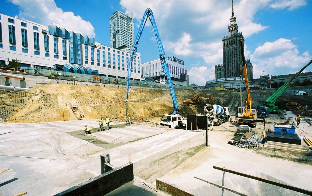
To minimise the costs of retaining walls, Arup kept the deepest excavation to the site centre. Slabs were kept at a higher level on the critical north and south ends and along the western perimeter. This resulted in several folds in the lowest slab, further complicated by the need for lift pits and lowered plant areas.
The Arup engineers decided that a continuous raft, free of movement joints, was the ideal way to control the risk of differential settlements and future cracking of finishes. As the loading intensity varied significantly, they used GSA to predict the piled raft settlements, which were significantly higher under the Skylight tower. Using iterative analysis, GSA optimised the design, equalising predicted settlements under the critical sections of the surrounding areas. The raft is typically 1.6m thick, varying between 2.65m under the tower to 1.0m under the lightly loaded northern end.
Basement structure
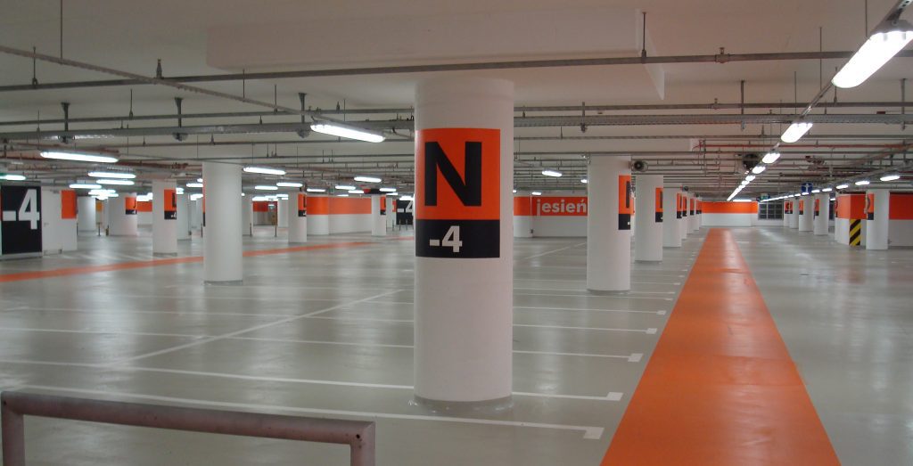
Due to architectural and functional constraints, the Skylight tower’s core is limited in the basement levels to only 40% of its area on the upper floors. The loads are transferred to a set of push-pull columns by very large shear walls, which are 3.7m deep and 1.6m thick. The complex geometry of this transfer structure required a special finite element analysis using GSA to understand its behaviour and design the reinforcement accordingly. The transfer structures in the basement and discontinuities of some columns from the upper levels resulted in complex beam arrangements. Arup’s design ensured there was no compromise to the car park’s functionality.
The atrium roof
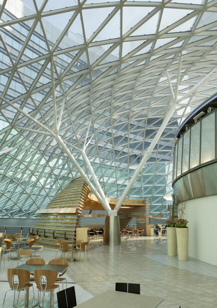
The spectacular glazed atrium was conceived as the heart of the project – the designers intended it to be an instantly recognisable architectural icon.
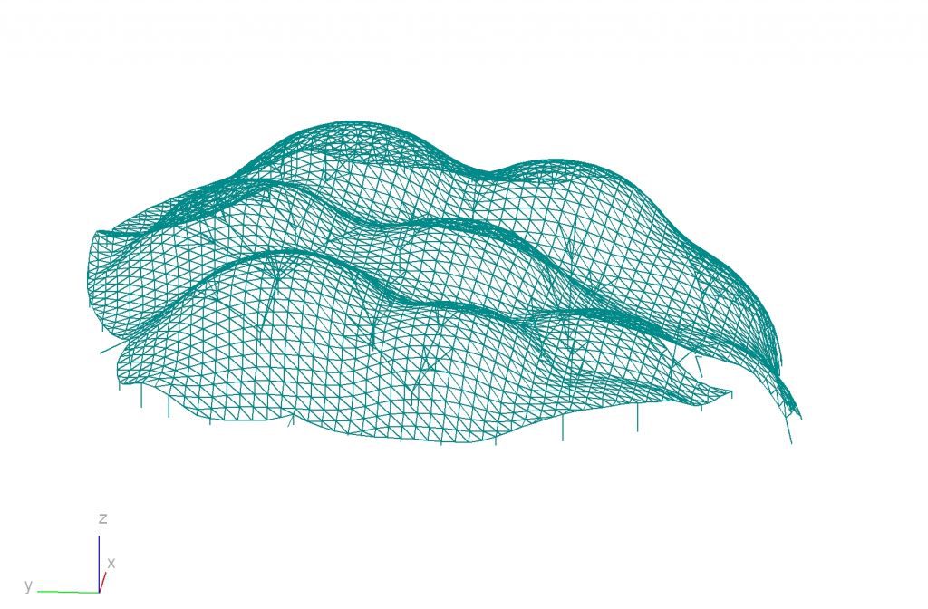
The overriding architectural ambition was for the whole roof to appear as a uniform mesh, with consistently-sized members. While this proved extraordinarily difficult, Arup achieved this by fine-tuning the GSA mesh design and its supports. The result was a continuous triangulated grid of steel rectangular hollow sections (RHS) of constant size, 200mm deep by 100mm wide, with wall thicknesses varying from 5mm-17.5mm depending on the forces in each member. In the end, each of the 2,300 nodes, 7,123 RHS members, and 4,780 glass panels had a unique geometry.
Structural modelling
The Arup engineers modelled the roof using GSA, with the support conditions imported from another analysis model of the reinforced concrete superstructure to ensure compatibility. They imported Jerde’s basic roof mesh geometry from AutoCAD and manipulated it using additional software to orientate every RHS member perpendicular to the bisector of the angle of the two glass panels it supports. Some Visual Basic routines were also developed to map the wind loads from the wind tunnel test directly from each pressure tap location onto every structural member.
As the design developed and the modelling results became available, the number of load cases and load combinations grew to include 14 wind load cases, 12 snow load cases, five thermal load cases, and 98 differential settlement load cases. There were 1,700 different load combinations for the ultimate limit state. The numbers of members and of load cases made this one of Arup’s largest GSA model analyses, stretching computing power to the limit.
Second-order and buckling effects
In addition to the static analysis, second order buckling effects were also investigated. Simple linear static analysis was based on the assumption that straight members were perfectly straight, but in practice, any member may have fabrication imperfections. When compressive forces are applied, these imperfections cause additional bending moments, known as P-Delta effects. Bending moments are also magnified because of buckling. These additional stresses in members are collectively known as “second-order effects”.
Structural design codes dictate that standard components like columns and the compression flanges of beams have sufficient stiffness to prevent buckling, and are strong enough to resist not only the applied forces but also any secondary forces that arise because of their flexibility. However, these rules do not cover structures as complex as the atrium roof, which have to be designed from first principles in a similar way to the development of the code methods. Fundamental to any procedure is determination of the buckling mode shapes, buckling loads, and their associated deformations. Simple estimates of these properties are very difficult and any approximation is necessarily very conservative, leading to a much heavier roof design.
Arup developed the procedure to check the second order and buckling effects of the atrium roof several years ago, but its use was complicated by the necessary size of the GSA model. Buckling and second order analysis are more complex and take much longer than standard linear static analyses. In this particular case, the buckling analysis took over 12 hours of computer time.
The buckling analysis for the atrium roof produced a series of buckling mode shapes, with a critical load factor for each mode. Because most of the roof is highly curved in two directions, no buckling modes affected everything. The significant buckling modes only affected local areas – generally an out-of-plane “dimple” comprising an area that is relatively flat, or long span, or highly loaded. From the analysis and subsequent calculations, the additional bending moments due to the second order effects were estimated for each “dimple” with a critical load factor less than 10. For most areas of the roof, these were less than 5% but in the worst cases, the moments were increased by 25%.
Another form of instability called snap-through buckling – such as when an umbrella blows inside out – was also investigated by comparing the small changes in curvature of the roof from the P-Delta analyses with the initial curvature. It was found that snap-through buckling could not occur under normal loads, because the roof is sufficiently curved to prevent it.
Model stats
- 10,150 nodes
- 7,600 elements
- 158 load cases
- 175 combination cases
Conclusion
The Złote Tarasy project involved one of the most complex structural analyses ever undertaken by Arup. The spectacular results were achieved through the power and flexibility of GSA.